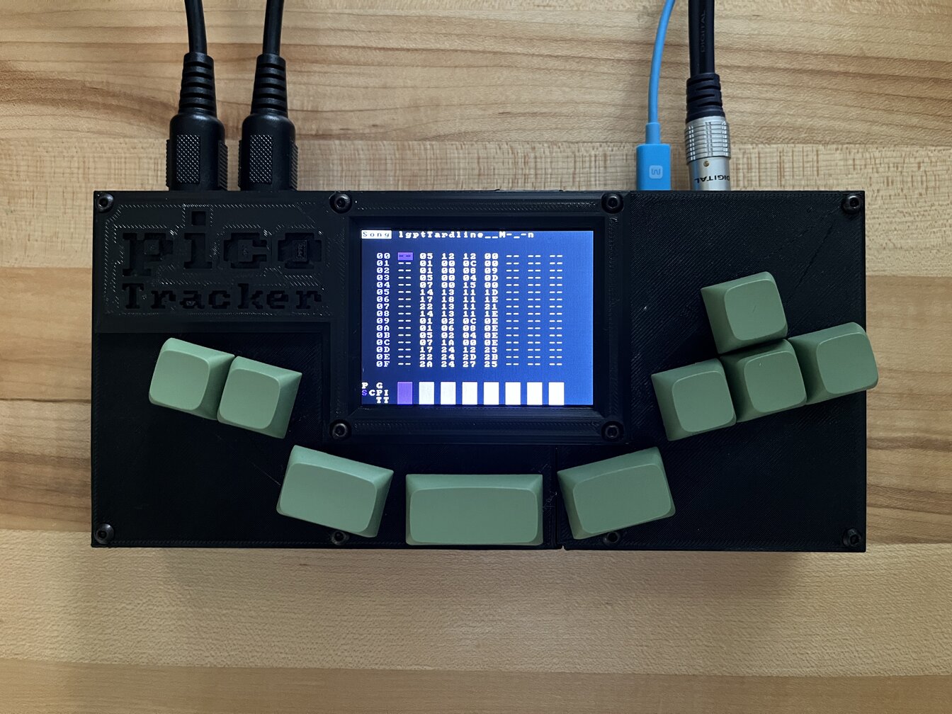
picoTracker
TL;DR
I ported LittleGPTracker to the Raspberry Pi Pico microcontroller and created an enclosure for 3D printing. The port has some limitations, some modifications and room to grow. Total cost of the picoTracker is $25 - $50 (USD) depending on things you may already have and where you source the components.
Introduction
I’ve been increasingly interested over the last years in music creation, synths, samplers, etc. While the music creation part hasn’t gone anywhere yet, I did want to create some kind of custom hardware synth/sampler. Since I’m usually better at adapting/remixing stuff than creating things from scratch (particularly on the software side), I’ve been exploring what type of software and hardware I could combine to make something nice. I first envisioned some kind of sequencer and sampler/synth based on an embedded linux and audio plugins, probably based on the Raspberry Pi CM4 and custom PCB. But the fact that you cannot buy a Raspberry Pi for any reasonable cost nowadays annoys me.
I don’t remember how, but at some point I came across LGPT, a software that I had never used, but that seemed interesting and obscure enough to spark my interest. First idea was to use my previous hardware “platform” idea and build something around that, but that seemed way too easy, compile on Linux, use some (probably available) driver for a DAC and screen and it’s done. Instead I thought that I could use the Raspberry Pi Pico as the platform, it’s available, cheap and the IC can be bought independently in case I’d like to actually build a full custom PCB around this. I didn’t do much due diligence to check if what I wanted to do was feasible TBH, I just kinda jumped right into it. I lazily called this picoTracker during development and the name stuck.
Final result is pretty good and I’m happy with it. Plus there’s still some room to grow in terms of CPU, so I have some ideas to improve it.
SPECS
- 8 song channels
- 128 chains
- 128 phrases
- 32 tables
- 16 Sample instruments
- 16 MIDI instruments
- 1MB sample memory
- 8 or 16bit samples up to 44.1kHz, mono or stereo
- 16bit/44.1kHz/Stereo audio output
Code, case and build guide can be found on github
Development
When I set myself to do this project, I set an objective to write about it at the end of it, so this is it. The idea to do a project in a language I’m not proficient in and a platform that I had never used was to learn and to challenge myself to make incremental updates even if I don’t have a clear picture of how exactly I could take it into completion. But more importantly, to finish it!. Over the last few years I took a habit of doing a lot of research into some idea, and abandoning it as soon as things turned a bit hard or I found something “more interesting”. This frustrated me so I decided to approach things differently, choose a project, power through the first ramping up phase and produce some tangible results, then move to something else. This project took a LOT longer than I initially expected, but has been extremely rewarding too.
I’m brain-dumping how I did this in order to reflect about the project and provide some overall idea to anyone that might want to do something like this. It has been a great learning experience and kinda proved to myself that no matter how little you know about any of the pieces, it can be done if you break it down into small enough pieces and make incremental progress. I approached this without being very proficient in C/C++, without having programmed or used a microcontroller since I did some assembly language project on a 8051 in university 20+ years ago, without knowing anything about audio programming, writing drivers, etc.
Sections
- Hardware
- Get something running
- Memory constraints
- Adding SD card support
- The audio
- raspberry Pi pico and clocks
- Project loading
- CPU constraints
- Further audio optimizations
- Random crashes
- RAM is not enough for samples
- Optimizations and customizations
- Final touches
- The case
- Future
Hardware
I already mentioned that I chose the Raspberry Pi Pico as the CPU of choice, for the rest of the hardware I made easy choices, I could optimize for better hardware in the final result, if needed. I wrote an MVP document for myself in order to lay out what I needed. I would need a DAC, a screen, MIDI In/Out, some input device and a battery. Initially this was going to be portable, didn’t go that route in the end, thou it would be pretty easy to add. In the initial MVP I didn’t add an SD card, what was I thinking?
For the screen I would need a 320x240 screen, which was the native resolution for LGPT. A quick search in Amazon and Aliexpress returned an ILI9341 controller based screens and another quick search returned some ready made driver for the Pico. Easy pick.
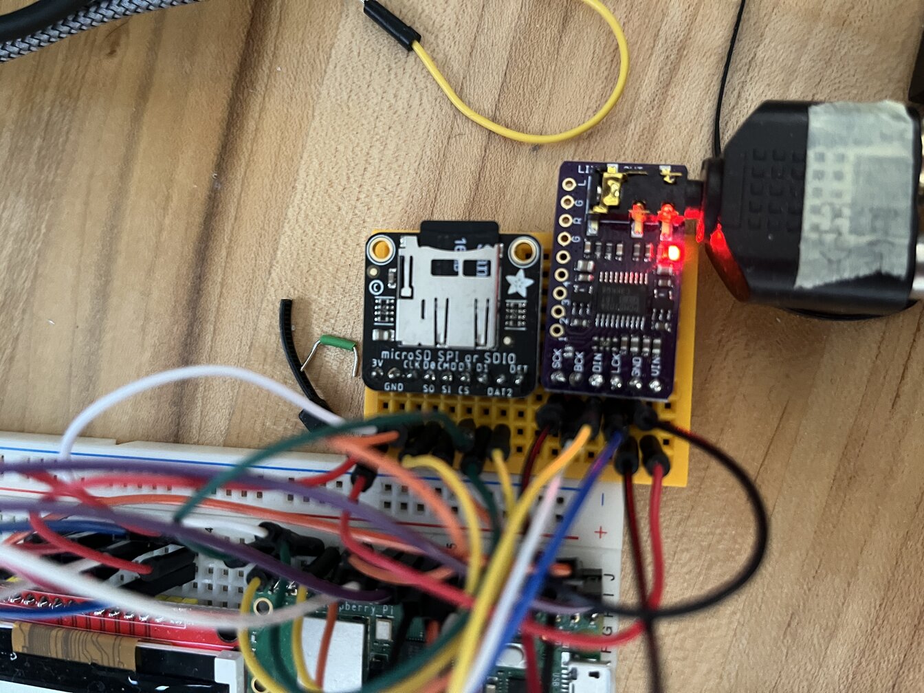
Searching for a DAC I found this extremely common PCM5102 based board, which is commonly used because it includes a PLL to generate it’s own MCLK signal. As it turns out, the Raspberry Pi, while having an i2s interface, doesn’t generate MCLK, so this board is pretty common among makers. While the Raspberry Pi Pico could generate the MCLK signal, the provided implementation does not, so this seemed like a good choice for me too.
MIDI was easy, it’s just using an UART port, so I just needed to find some board for the physical interface.
Early on I figured that I would actually need an SD card and based on a cursory look at what was provided for the Pico there was an implementation of SDIO, so I searched for a breakout board that supported it.
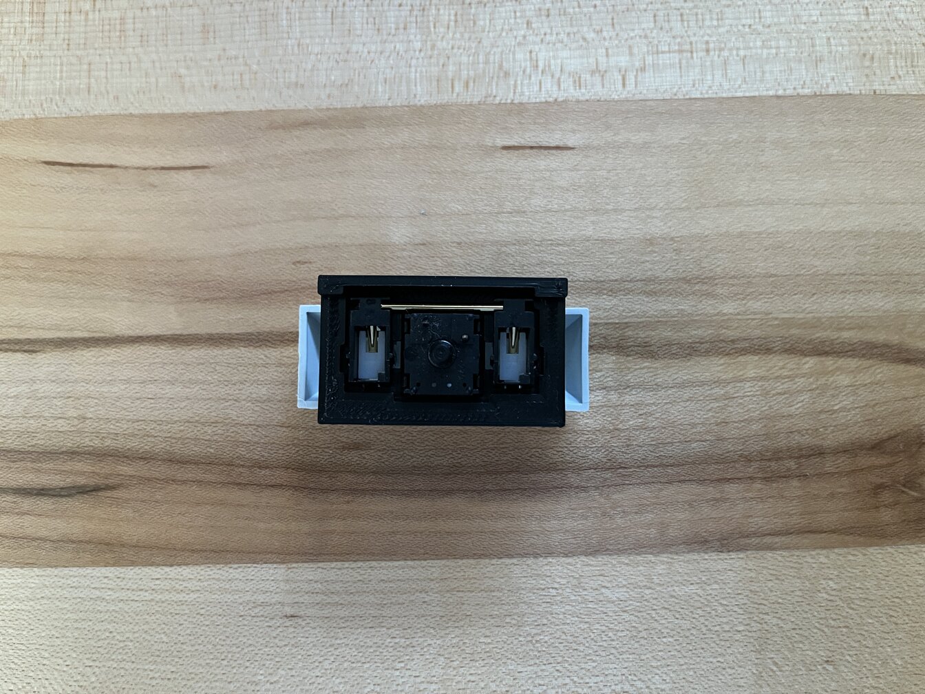
For switches I went with Cherry MX style switches. Having built a custom keyboard before this was an obvious choice. They are cheap, widely available and you can easily customize the look of the keycaps.
Next I needed to see how I would connect everything. I would need:
- 3 pins for i2s (without MCLK)
- 2 pins for MIDI (on an UART)
- 2 pins for debug UART (on another UART)
- 6 pins for a 3x3 keyboard matrix
- 6 pins for SDIO
- 6 pins for the screen (RX included, which wasn’t needed in the end)
This used 25 of the 26 GPIO on the Raspberry Pi Pico board (the RP2040 chip has a few other GPIO that could be used).
Final iteration I changed this a bit:
- 4 pins for i2s (with MCLK, thou not currently used)
- 2 pins for MIDI (on an UART)
- 9 pins for a 9 keys keyboard
- 6 pins for SDIO
- 5 pins for the screen (no RX)
This uses the 26 GPIO on the Raspberry Pi Pico
Hardware ports used are as follows:
- MIDI uses UART0
- i2s uses PIO0
- SD uses PIO1 for SDIO or SPI0 (dedicated) for SPI
- Display uses SPI1 and GPIO
- Keyboard uses GPIO
Get something running
As with a number of things about this project, I was lucky that it was built in a way that allowed it to be easily built for different platforms from the start. While this helped in the beginning, I think it was slightly detrimental in the long run, since I tried to keep myself too isolated into the platform specific code for too long and trying to make things work without touching the main code too much. In the end I decided to just do whatever I wanted across the codebase and that gave me more freedom to explore more, fix things around the codebase, customize, etc.
The first thing I did was to get the code compiled around the Pico C SDK. I had no idea about the code, what was necessary and what not, so I copied another platform “adapter” and went from there without caring too much about the details. The only thing I wanted at this point was to get the code compiling for the target platform. My first exploration of the project showed that I would need to replace SDL, as all ports depended on it and I would probably need to have some support for threads, so I settled on including FreeRTOS in my initial port (this assumption ended up being incorrect). The method of porting the code was kinda like playing whac-a-mole; I found the entry point of the code, included this into the Pico SDK build system (cmake), compiled and checked what failed/was missing. Then I would go into that file, include it, see if it needed any modifications, etc. This was a bit annoying but gave me a sense on how the project works and what depended on what other thing. I’ve never been very good at reading entire codebases in the vacuum and being able to figure out what’s going on. This process required me to provide replacements to certain SDL features like timers, drawing, etc. The modular aspect of the project helped a lot at this stage because things were already set up in a way that you could replace certain drivers, like audio, with “dummy” drivers, so I could defer that for later.
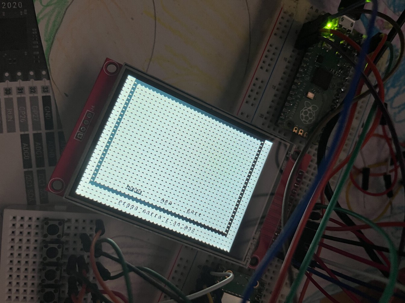
The first hardware interface I included in the project was a screen. I used this driver as a base, and over time I added to it. As this was the first thing I was using for interaction with the project, I added some nice screen message “Booting…” to know that something was happening. I added a message after each component was loaded, to know how far along I was. After some time and a lot of commented out code I got my project to compile and to show that boot message, and that’s it.
I was at this point just attempting to compile and manually copy the UF2 file over USB, this was not going to fly in the long run. Soon after I built a picoProbe and started loading code via the SWD interface with OpenOCD, learned to debug with GDB and used the UART IO interface.
Another thing I lucked out about at this point is that the project provided a character based interface, rather than graphical and this fit perfectly well with one of the modes of the screen driver I had found. Not only this made character only mode easy to adapt into the driver, but it also meant that I didn’t need a full screen buffer to draw the screen, which would have taken 320x240x2 (153.6Kb) of memory. Instead, I just needed a 40x30 char buffer, I would realize soon enough how important this was.
The first commit I did stated “Initial Pico port commit. Build ok, screen ok’ish, no sound, inputs, filesystem or MIDI. RTOS built but not integrated.”
Memory constraints
The first (not so) obvious thing that happened is that memory was a problem. “Obvious”” because if I had done some due diligence it would have been pretty obvious that 264K of RAM would not fit the LGPT code. “Not so obvious” because I didn’t have much idea about what I was looking at and how to debug any of this. I think that the fact that I didn’t do my due diligence in this aspect was lucky, since I might have been discouraged to even attempt to do this if I figured it wouldn’t fit. Of all the platforms to which LGPT has been ported, the smaller one had 4MB of RAM.
In short, LGPT requires:
- A 20K samples long audio output buffer (80Kb memory)
- A 50 buffers long ring buffer, with each buffer being variable and up to over 4KB long (>200Kb)
- Other mix buffers here and there totalling ~30Kb
- 80 Sample instruments, each using ~7Kb of dynamic memory when loaded (560Kb)
- 3500 long feedback buffer for each song at double resolution (224Kb)
- 16 MIDI instruments, each using ~1Kb of dynamic memory when loaded (16Kb)
- The sequencer data structures (Song/Chains/Phrases/Tables) totalled >100Kb
- Number of other random things like screen buffers, UI buffers, STL, etc (50Kb - 100Kb)
- Additional memory to load and save projects in XML format, full DOM is loaded for >200Kb project files
So at least around 1.5Mb and that’s without taking into account any sample loading into RAM. And to make things worse, the project is FULL of dynamic allocations, which is generally a problem in a platform with so little memory. The only relief in terms of dynamic allocations is that most of it happens at project loading and afterwards, while there are a lot for GUI and stuff, they seem to be not too large and not leak memory (which is another problem I encountered).
At this point I stripped down a lot of things, minimized the number of instruments started, removed MIDI instruments, made the sample instruments feedback buffer super short (I ended up removing this feature), and decreased the number of Chains, Phrases and Tables. Audio buffers were not a problem at this point because I wasn’t doing any audio, and since the allocations were dynamic, that memory was simply not being used. This allowed me to advance into the (empty) project loading screen.
Adding SD card support
In my original MVP idea I hadn’t included SD card support, since it seemed possible to run the project without actually needing to load or save files. The problem tho was that I had never actually used LGPT, add that to the list of poor due diligence before starting this project. It became obvious early on that I would have to be able to load something in to be able to compare to a known project running in a working device, rather than trusting my ears. Especially because I wouldn’t be just comparing sample playing but a lot of effects and transforms where I wouldn’t know what’s the expected outcome.
For this, I investigated a bit and came to the conclusion early on, given the memory constraints, that I would need to somehow stream the files from the SD card, and that meant fast SD read speeds. I decided to try to go with an SDIO implementation, which in theory would be faster than using SPI. The pico extras repo provided an SDIO implementation but it seemed to be incomplete. Then I found the ZuluSCSI project that provided another implementation, so I decided to try it out. In terms of what filesystem implementation to use, it was easy, I just used SDFat which is what the ZuluSCSI project used. As it turns out, the performance wasn’t that good (probably a problem with my implementation), but I decided to kick this issue into the future, I had a working filesystem from where I could load a project and that let me advance a bit further.
As of the first release of the project I haven’t come back to this. I later found out that a simple SPI implementation was giving me even better speeds (again, probably my own implementation/port problem), so I removed SDIO support in the latest built, tho it can be enabled. My plan is to revisit this at some point and try to get SD card streaming of samples working.
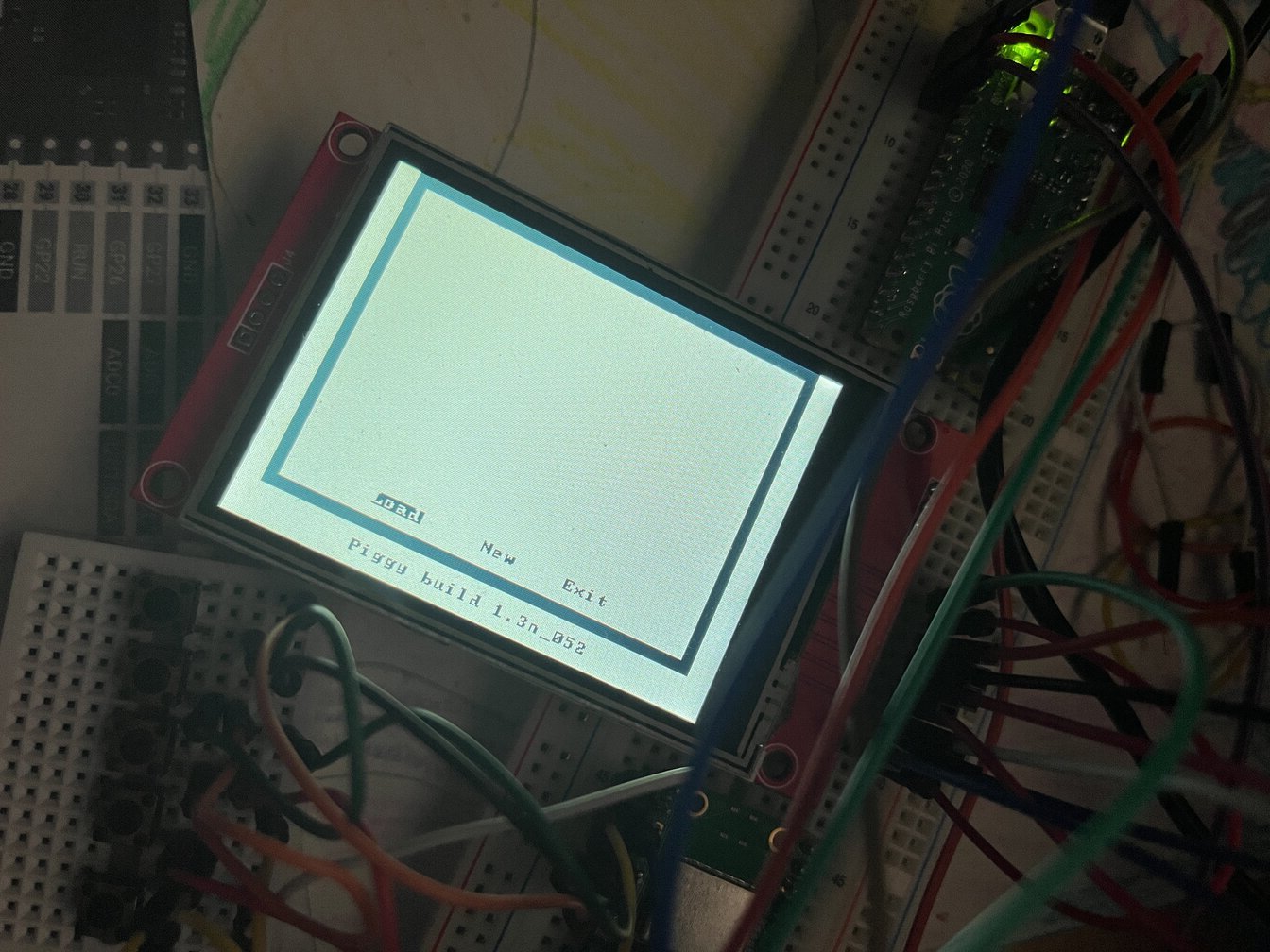
At this point I was ready to try to load some project in. I decided that the project that comes with the Windows version of LGPT, M-.-n : Tardline was a perfectly good place to start (this is what you hear in the video at the top of the page). It had the added benefit of using ~10Kb of sample memory only, so I could squeeze it to RAM. I manually modified the XML version of the project to make it as small as possible (I would still need to load this XML into ram in order to load it). This still didn’t work, the XML parser was using way too much memory, I decided to defer for later. I could still create an empty project without an XML config file, so this way I could reach the main screen.
The audio
It was time to move into playing something. This part was probably the most difficult for me, it took WAY too much time. Looking back, I’m not entirely sure why, it wasn’t that hard, but I had no experience at all on audio projects and I had no idea how an audio driver was supposed to work. Had to figure out what was a ring buffer, why it was there, how it worked, etc. What the driver was doing, the purpose of the main buffer, a mysterious blank buffer, etc. Plus the audio driver ran in a thread, I had integrated FreeRTOS support for that, but had never used it and wasn’t sure how to do it.
This is where I integrated the I2S implementation of the pico extras library and had to work with the audio API provided, which wasn’t documented anywhere. An additional complication is that I wasn’t even sure what data format was expected by that API, and what was used by the project itself. Most of these are pretty obvious now, but at the time there were a lot of things that I had to figure out at once in order to get any results, which made it hard. In the end, the code for the driver is actually pretty short and simple. A further complication included the fact that the Pico would hardfault with no Backtrace at all if I printed any messages from the main driver routine. Later on I discovered that this wasn’t due to some weird limitation on the Pico, being able to print out messages from an IRQ handler or anything like that, but yet another of the many memory issues I found along the way.
While I believe I spent some time trying to make FreeRTOS tasks work at this point, I figured out pretty early that I didn’t need that in order to get some sound out, so I defered that into the future and ended up never using it. (I did end up running the driver in the other pico core tho, as a later optimization)
My main objective here was to get some sound out. I won’t go into the details on the back and forth but the first version of the driver resembled very closely the SDL driver implementation and didn’t work very well. The main sounds were there, all chopped up and distorted, but hey! that’s a milestone.
For a while after this I chased a red herring in playback speed. The first sounds I was playing where from the sample preview dialog, given that I couldn’t load projects yet. The sample I was playing was playing at 4x speed and I couldn’t figure out why. It turned out that the sample was sampled at 11025Hz and LGPT simply does not do sample interpolation in this mode (it does when samples are played as part of a project), so this was being played as if it was 44100Hz, which was my main output sample rate. (-‸ლ)
raspberry Pi pico and clocks
When I started to build the audio driver and read the code, I figured that there were some optimal frequencies at which to run the Pico in order to have precise frequency dividers, which would presumably yield the best sound quality. It seemed reasonable to pursue this path, but I honestly don’t know if where this landed made any difference in audio quality. ¯\(ツ)/¯
Either way, this led me to look at the clock’s hardware a bit deeper and figure out how I wanted to run it. I had to adjust the clock speeds of multiple periferials as well as the main clock speed and this presents some problems since there are multiple ways to achieve the results and multiple interdependencies and restrictions between them. All of this is described on the RP2040 datasheet.
There are multiple clocks that we care about:
- System: As fast as we reasonably can
- SDIO: between 25MHz and 50MHz (slow and fast modes respectively)
- i2s: 44.1 kHz × 16 × 2 = 1.4112 MHz
- DEBUG UART (0): 115200 (not needed for prod binary)
- MIDI UART (1): 31250
- SPI (screen): 48MHz
- USB: 48MHz
I approached this by searching suitable frequencies for i2s and then adjusting the rest around that. There are two PLLs in the Pico, one for the system and the other one for the USB. Other clocks can generally be depended upon one or the other and be divided as needed. Since USB needs to operate at 48MHz, it didn’t seem like a good target to be messing around with, so I decided to adjust the System PLL, depend PIO devices upon this one by dividing as needed and depend the other peripherals on the USB PLL.
The datasheet presents how the PLL frequency is derived and some restrictions on the configuration parameters:
PLL Freq = (FREF / REFDIV) × FBDIV / (POSTDIV1 × POSTDIV2)
- Minimum reference frequency (FREF / REFDIV) is 5MHz
- Oscillator frequency (FOUTVCO) must be in the range 750MHz → 1600MHz
- Feedback divider (FBDIV) must be in the range 16 → 320
- The post dividers POSTDIV1 and POSTDIV2 must be in the range 1 → 7
- Maximum input frequency (FREF / REFDIV) is VCO frequency divided by 16, due to minimum feedback divisor
Another consideration is that a higher VCO is better to minimize jitter (at the expense of higher power consumption). The main constraint I was looking for was to make the system clock be divisible by 44100 / 4 = 11025 (Hz) (the why of this lies in making the PIO clock divider for the i2s implementation exact)
Plugging all these constraints into an ugly brute force script that basically calculates every single possibility of parameters while staying within the constraints yields:
35.28MHz  REFDIV: 2 FBDIV: 147 (VCO: 882.0 MHz) PD1: 5 PD2: 5
44.1MHz   REFDIV: 2 FBDIV: 147 (VCO: 882.0 MHz) PD1: 5 PD2: 4
55.125MHz REFDIV: 2 FBDIV: 147 (VCO: 882.0 MHz) PD1: 4 PD2: 4
88.2MHz   REFDIV: 2 FBDIV: 147 (VCO: 882.0 MHz) PD1: 5 PD2: 2
110.25MHz REFDIV: 2 FBDIV: 147 (VCO: 882.0 MHz) PD1: 4 PD2: 2
176.4MHz  REFDIV: 2 FBDIV: 147 (VCO: 882.0 MHz) PD1: 5 PD2: 1
220.5MHz  REFDIV: 2 FBDIV: 147 (VCO: 882.0 MHz) PD1: 4 PD2: 1 <- Chosen
441.0MHz  REFDIV: 2 FBDIV: 147 (VCO: 882.0 MHz) PD1: 2 PD2: 1
I chose 220.5MHz as the frequency to use. This is higher than the stock 133MHz, but the pico is known to be pretty good at overclocking and I felt I would need the processing power. This frequency is still well within specs of the QSPI flash used as program memory, which can run up to 133MHz (QSPI peripheral frequency is half of system frequency). One thing that it’s immediately obvious is that the VCO is not very high, which is ideal to minimize jitter. So, is jitter bad enough as to make the exact divider for the i2s clock optimization meaningless? No idea…
If I wanted to use a higher VCO at the expense of an inexact (but within 0.0001% of the ideal) i2s clock we could use:
239.0MHz (exact needed: 238.99995MHz) REFDIV: 2 FBDIV: 239 (VCO: 1434.0 MHz) PD1: 6 PD2: 1
This is still below the QSPI Flash memory limits and works quite well, plus it gives us an 8% speed boost.
If we wanted to maximize clock speed, we could use 266MHz (to the limit of the Flash memory), and it would still be within 0.001% of the actual frequency needed. And use almost the highest possible VCO freq.
266.0MHz (exact needed 266.000175) REFDIV: 1 FBDIV: 133 (VCO: 1596.0 MHz) PD1: 6 PD2: 1
Ultimately, I’m not sure if any of this is super important for sound quality and could overclock a bit more in the future for some speed boost. For a custom PCB there are further options depending on the crystal used in order to achieve higher exact frequencies, but in that case the USB frequency would suffer and I’m unsure how much wiggle room is there. Furthermore, on a custom PCB a flash memory with higher ratings could be used too. For example, high VCO, close to 266MHz and exact divider with a 13.5MHz crystal:
264.6MHz REFDIV: 1 FBDIV: 98 (VCO: 1323.0 MHz) PD1: 5 PD2: 1, crystal 13.5
Project loading
I was advanced enough that I had to tackle project loading, and loading the whole XML into memory for loading was not going to cut it. I approached this pretty naively and never really looked into why the whole document was being loaded into memory, the answer is that the XML parser was creating a DOM for it. I initially replaced TinyXML for TinyXML2 which said it used much less memory, but it still failed. Then I used pugiXML which was another “low memory usage” parser to be met with the same results. Until I looked a bit more into it and understood that what I needed was a SAX parser, where a DOM would not be created in the process. I found a library called yxml and used that. That worked wonderfully and at this point I could load the whole project into memory (with just enough Chains, Phrases, Tables and Instruments so that the project would fit). Including TinyXML2 into the project didn’t go to waste because this new version has a streaming saving method which doesn’t create a DOM in the process and that I ended up using for saving.
CPU constraints
It was time to do a bit more of profiling of the CPU usage, given that things seemed to be working well, but the CPU was clearly not keeping up. I soon encountered two issues:
- Each screen rewrite was taking ~36ms and some project screens were updating up to over 40 times per second, this was clearly not going to work
- Later discovered that my lazy matrix scan implementation was taking 3ms per scan, and scanning happened on each main thread loop
The first issue had an obvious fix. Most of the screen updates were updating a few characters on the screen. Either the song progress counter, the cursor showing the place in the Song/Chain/Phrase/Table, etc. For this I wrote a partial screen rewrite implementation which would take less than 1ms in a typical screen rewrite of a few characters (at the expense of slightly longer full screen writes). Huge win for relatively little effort.
The second issue was even simpler. When I first created the input system for the picoTracker I did some planning in terms of IO and decided to go with a 3x3 matrix for the 9 keys I needed instead of spending 3 more GPIO for a simpler implementation. Problem with the matrix scan implementation is that it works by flipping one column (or row) GPIO at a time, waiting for the pin to switch, and then scanning the corresponding rows (or columns). That “wait for the pin to switch” was the problem, I had lazily just set that sleep time as 1ms, which was the minimum unit for the sleep_ms API call. Luckily there was a sleep_us call and I soon found out that about 4us was all that was needed to wait for the GPIO to switch.
In the final implementation I dropped the key matrix and dedicated one GPIO per pin in order to make the build easier (no diodes), so the second point became irrelevant.
Further audio optimizations
There was something about the audio driver that was still bothering me. The whole audio API for the Pico seemed too complex, unreliable (although it might have been me not using it right) and was wasting even more memory on additional buffers. What was really going on under the hood? Did I really need another layer of buffers?
I dug into the code and I soon found out that most of the API was just boilerplate to support multiple input and output audio modes (and many of the combinations were not even implemented) and the actual method by which the samples were sent to the hardware via DMA. Funny enough, after reading in the datasheet a bit about DMA and how it worked, I found it easier to understand the lower level implementation than the higher level Audio API (which had no documentation at all).
It basically goes something like this:
- Choose the DMA word size (4 bytes in out case, since each sample is 16bit and 2 channel)
- Set an IRQ handler that will trigger when the DMA transfer is over (this is the main entry point into LGPT in order to calculate a new buffer)
- Enable the IRQ
- Start a DMA transfer from a buffer in memory
From that moment on, there is not much to do. Each time a DMA transfer finishes, it triggers an IRQ which calls the instrument rendering and mixing methods to fill the output buffer, we call a new DMA transfer from that new buffer, and over again. The whole thing is self sustaining and it’s basically a parallel code path running off IRQ, pretty neat.
Random crashes
Everything was working pretty well but I still had random crashes here and there which ended in hardfaults in the debugger, without any backtraces. At this point I did have some intuition of what could be going on, memory, it’s always memory problems! I started to suspect that the stack was being overflowed. The Pico SDK has a compiler flag named PICO_USE_STACK_GUARDS which according to a Raspberry Pi engineer in the forum, might or might not catch a stack overflow. It turns out it did catch some for me, but not others. But it gave me a hint that something was going on there. I had to find a way to conclusively understand if the stack was being overflowed.
Default memory layout for the Pico:
| Name | Use | Size | Address |
|---|---|---|---|
| SRAM5_BASE (scratch X) | Stack Core0 (growing down) | 4KB | 0x20042000 |
| SRAM4_BASE (scratch Y) | Stack Core1 (if used, growing down) | 4KB | 0x20041000 |
| SRAM_END | 0x20040000 | ||
| SRAM_BASE | Heap (growing up) | 256KB | 0x20000000 |
Since by default the stack for core0 is in the Scratch X memory space, I figured I could fill up the Scratch Y memory space with a zero initialized array and periodically check if the array has changed values at any point. Sure enough, after project loading this area of memory changed values, the stack was being overflowed. As it turns out, there was a buffer in LGPT for printing out debug info that was 4KB(!!!) in size. The default Pico stack is 2KB in size, and I had set it to 4KB.
RAM is not enough for samples
At this point everything was working pretty well but I still had the problem of the samples. I had tried briefly to make them play from the SD card and it didn’t work (could be because it’s hard to do or because I didn’t know how to). I also couldn’t spare any reasonable amount of RAM to store samples, so what should I do?
I didn’t want everything to go to waste so I started to explore the idea of incorporating synth engines and making it more like LSDJ. And since I was thinking about LSDJ I immediately thought it would be nice to have another type of retro sound, a C64 SID. I compiled reSID into the project but it was using way too much static memory, plus the CPU usage was too high. I would still work but would be just one or 2 SID instruments max. Next I tried:
- A precomputed version of reSID which used much less memory
- cSID
- crSID
- tinySID
- some other random SID implementation
crSID is pretty promising, it uses fixed point math so it’s ideal for the Pico which doesn’t have a FPU. Performance wise it’s pretty good, it still uses 1.5x - 2x as much CPU than one sample instrument, but totally doable.
Just then it occurred to me that I could actually use the Flash memory of the Pico for loading samples into it. It’s not huge (2MB total flash) but much better than the few KB I could dedicate in RAM, and it would be enough for a pico Tracker. I would have at least 1MB free (in practice it’s more like 1.6MB, but the official specs are 1MB).
For the sake of taking this project to completion, I abandoned the idea of synth engines for the first release, but will probably follow up on it and will probably include a number of other emulated synth chips, we’ll see…
Optimizations and customizations
At the start of the project I wanted to do a pure port of the code into the Pico and was pretty hesitant to touch any of the core code. But as time went on, it became evident that there were a number of things that could be improved in the codebase. I barely scratched the surface, but I have fixed some bugs, including some memory leaks, which were a show stopper in such a memory constrained device. I also fixed almost all the compiler warnings in GCC and LLVM. At some point I wanted to remove all dynamic allocations and do most with static allocations, but this turned out to be pretty hard to do, I did some tho.
A significant memory saving modification I made was to convert the command structure in Phrases and Tables from 4 bytes (encoded as a FourCC 4 byte variable) into 1 byte and thus saving ~17KB of memory. There are about 70 commands, so this still allows it to grow up to 256 commands. The way I did it was maybe not ideal, just replaced the FourCC 4 byte type with a 1 byte type and statically mapped the old defined commands into the byte sized variable with a lookup table. It works and didn’t have to mess much with the rest of the code ¯\(ツ)/¯
I also changed the layout for the project, the original layout is 40x30 (8x8) chars which to me is pretty small. So I experimented doing it 32x24 (10x10) chars. I introduced a 10x10 font but found out that even if the fonts were bigger, it didn’t look less crowded due to how close the fonts were to each other. Interestingly, I think that using the 32x24 layout, but separating a bit more the 8x8 fonts worked pretty well. I quite like the final layout, but thinking about some of the features I’d like to introduce I wonder if I’ll end up reverting it, we’ll see. This layout change helped save some memory too, always welcome.
Final touches
Before release I did a number of commits in order to make it (hopefully) fully usable.
- I found and fixed a memory leak related to sample browsing
- Couldn’t flush out all of the bugs and leaks related to getting out of the project, but I set an ugly but effective workaround. Loading a new project causes a reset, so we start fresh
- I realized that the case I built doesn’t give access to the button to put the Pico into Bootsel mode in order to upgrade the firmware. But I found a way to do this in software, so in theory, we’d never need to access that button other than the first time we flash it
- Wrote the README.md, MANUAL.md and DEV.md docs
- Finalized the DIY schematic
The case
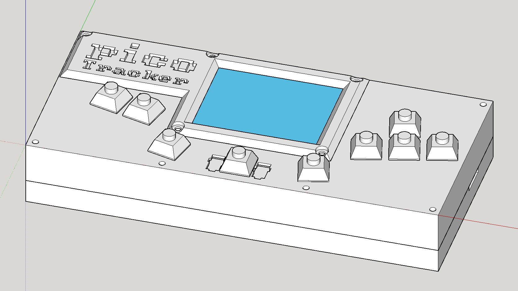
I worked on the case in parallel to the main project. I went with my gut here, no idea what I’m doing, did something that seemed to make sense. My thinking was that I wanted to minimize the amount of components, and specially components that would be hard to specify and/or source. For this reason I didn’t want to use screws to put the PCBs in place (plus the audio one didn’t have screw holes in it). I came up with a solution to “sandwich” the PCBs in place between the top and bottom case. The size I chose is quite arbitrary, a custom made stand I made for my music gear had a space for a Syntakt device in case I may want to buy one in the future, the width of a Syntakt became the with of the picoTracker. For height I did 10cm, seemed like a nice round number and it fit all the components and keyboard layout. Speaking of keyboard layout, I went with a typical ergonomic keyboard angle, seemed fitting since I’m using Cherry MX switches. I thought if arrow keys should be to the right as a typical keyboard or the other way round, settled for the former.
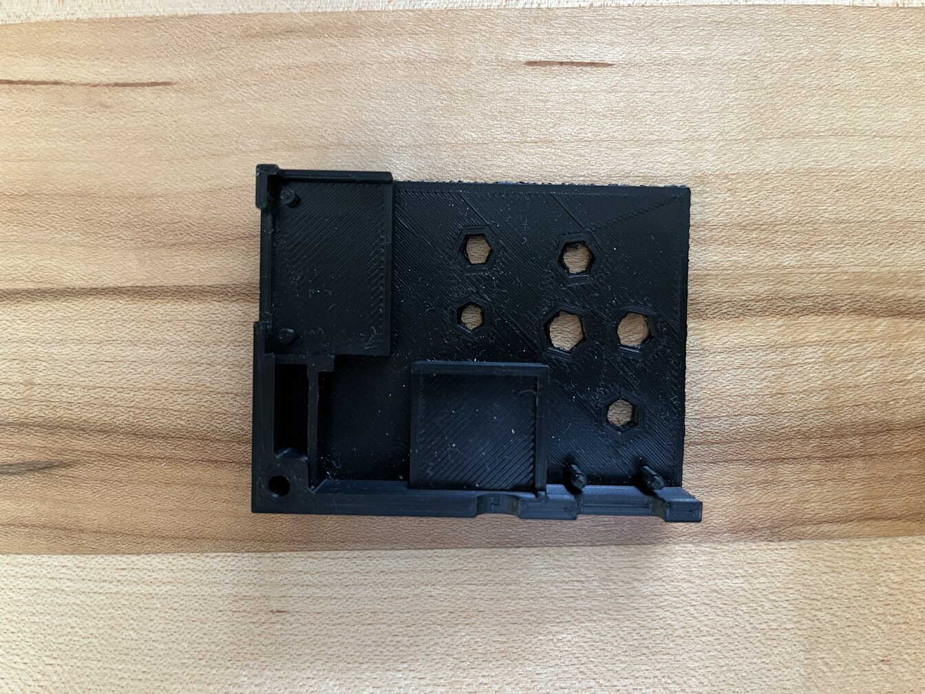
In order to do the placement of parts and build the case around it I used specifications from manufacturers about the PCB dimensions, screen size, etc. For components where this wasn’t specified I did as precise measurements as I could with a caliper. This got me very close to what I wanted, I built the case following this information.
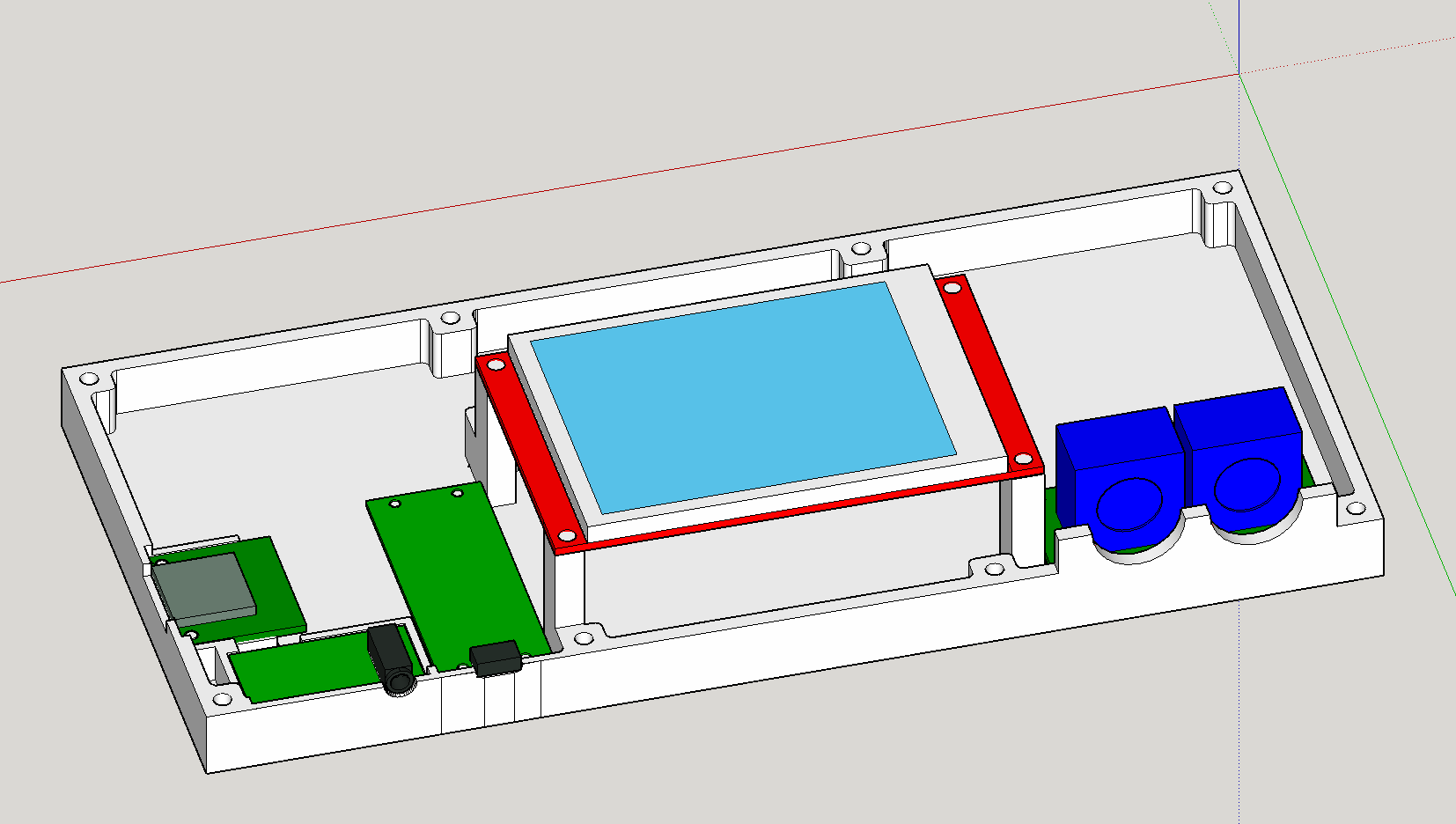
Depending on the mounting options in the PCB (or lack of it) I built an appropriate housing, keeping in mind where I would need to solder cables to them. The pico has 4 mounting points, so it’s not necessary for it to have a base (thou it could help in order to stick it and make soldering easier, might change it in the future). The MIDI board has components underneath, so no base is possible, plus has 4 mounting points. Audio board has no mounting points and SD card has only 2, so I created a base to give better support.
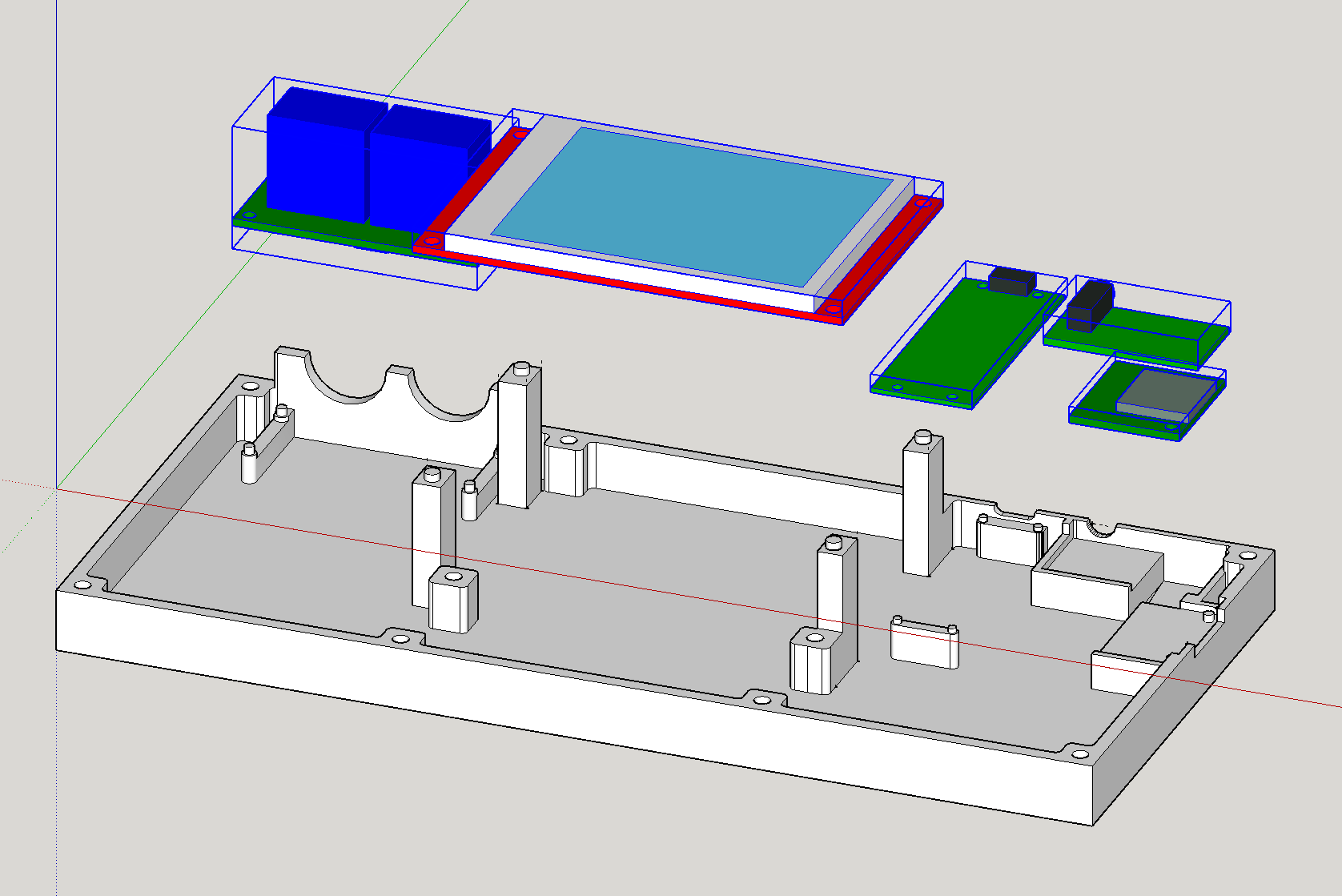
In the case of the MIDI port I figured there might be enough insertion forces that it might break the mounting holes supports, so on the top case I created an enclosure that supports the MIDI ports against horizontal forces.
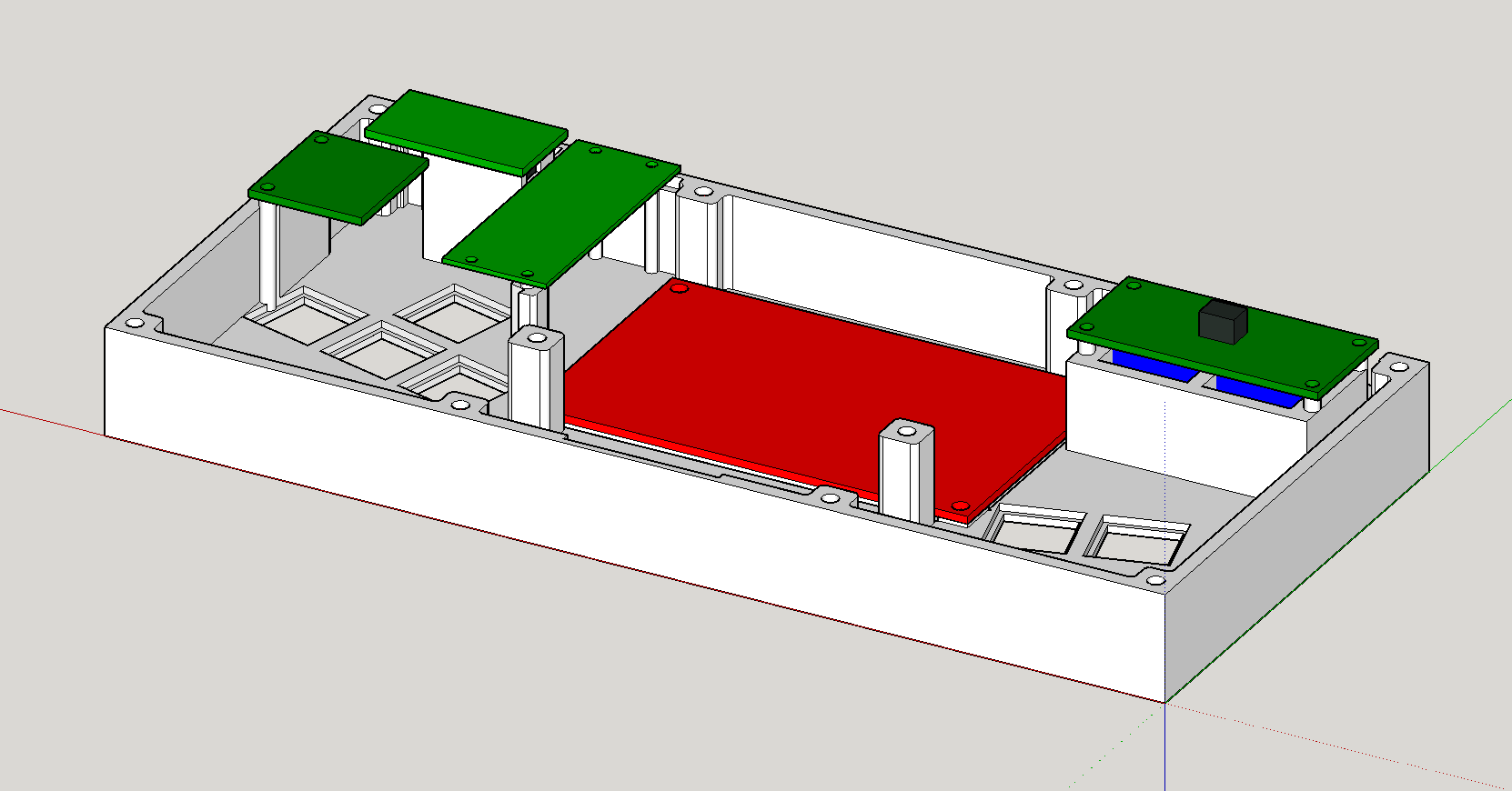
In order to iterate quicker and test different features of my enclosure I printed smaller subcomponents in order to test how well they fit. The approach of modeling the PCB boards has been pretty good, as I didn’t have to make many adjustments after the initial case modeling.
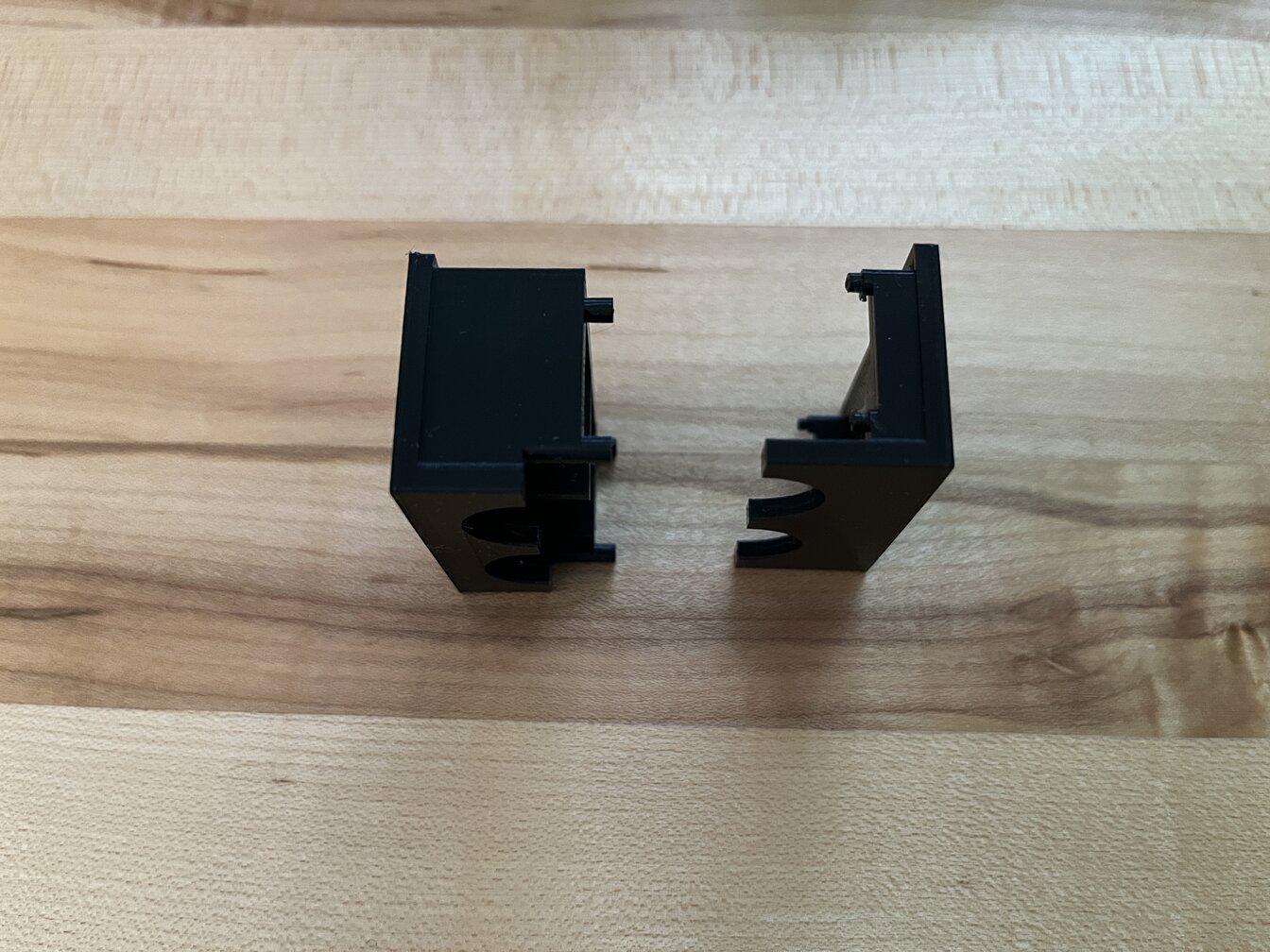
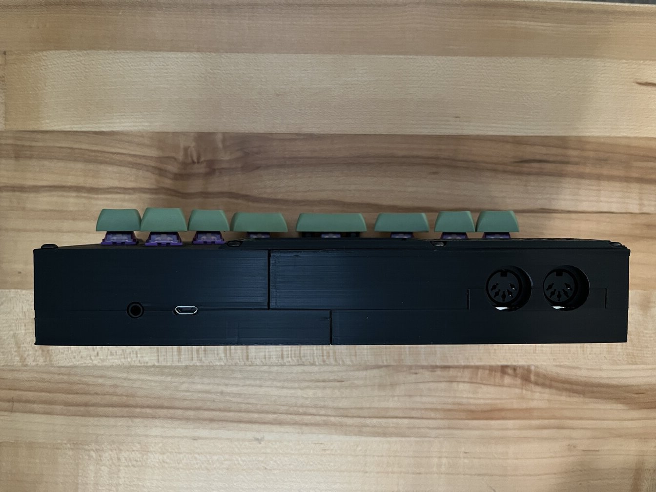
Fit of the side ports came out better than I expected.
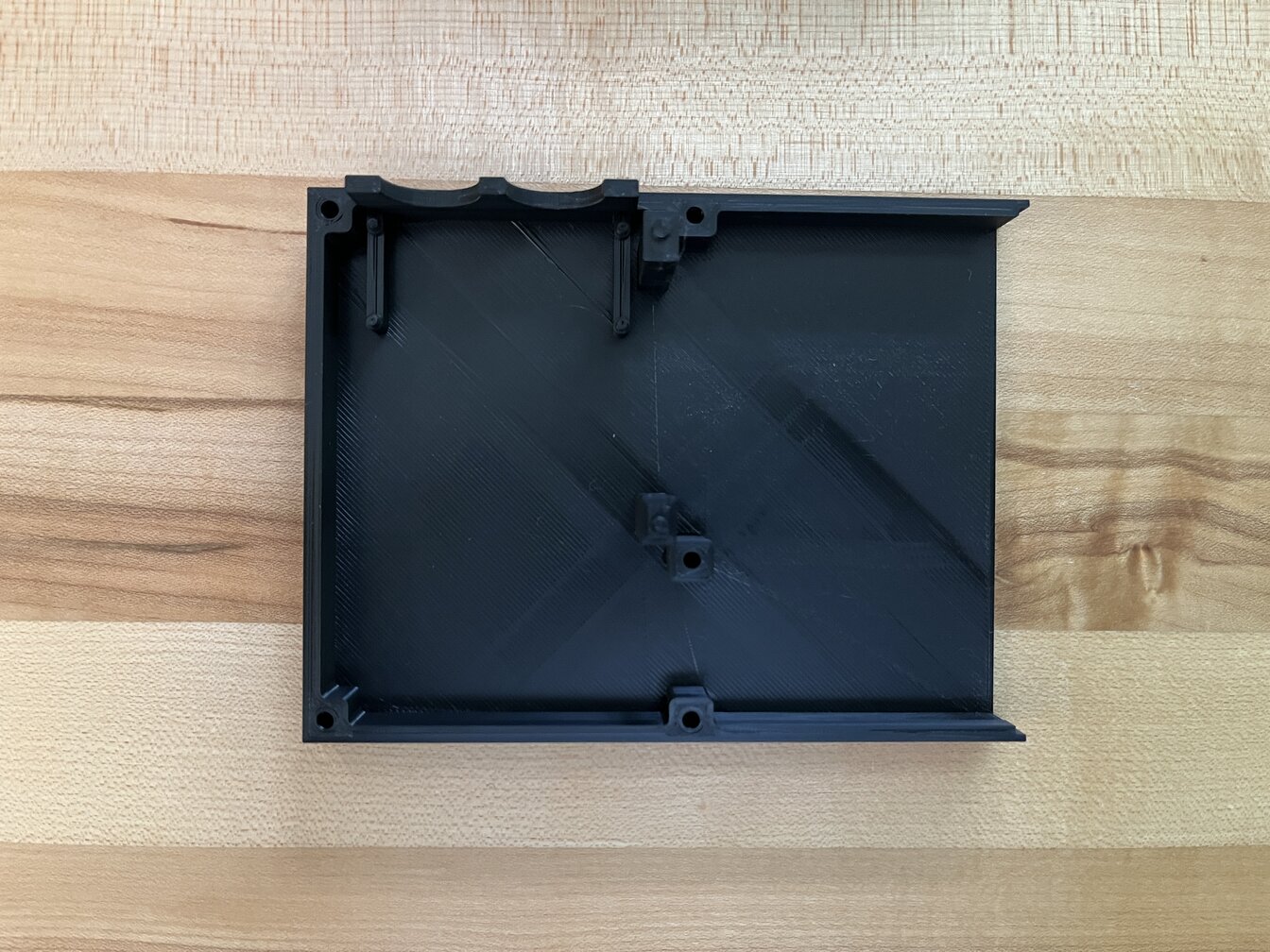
A (half) print of the bottom case (my printer bed is not big enough)
Final build
Future
There are a number of incomplete software features that are probably pretty quick to implement, like MIDI IN. Adding additional synths shouldn’t be too hard either and it’s fun, so it’s very possible I’ll follow up on that. Adding support for USB MIDI shouldn’t be too hard either, but I haven’t looked into it. I’d love to implement the SD streaming feature, but I feel a bit out of my depth on this one. Using both cores to render instruments would be great too, core0 currently sits mostly unused.
From a hardware point of view, I wanted to make a PCB for it but it already took too long and I wanted to release it. I’ll probably make it, and would like to add some hardware. The final product should ideally have headphone output, have volume control, allow for USB MIDI and separate power, etc. I wanted to make some PCB ready for manufacturability for a while, so this is a good opportunity. I’m just having fun with this, so there are no plans to commercialize this in any way.