picoTrackerPortable
TL;DR
picoTracker is a DIY music tracker that can be built with off the shelf components and built by soldering all the components together using wires, this is laborious, prone to errors and limits some of the design choices. I set myself to create a PCB for the project that could be easily built to make things easier. This set me off in a different direction and ended up creating a portable version of the picoTracker.
Introduction
When I first created picoTracker I thought I’d do a prototype with ready made parts and then I would do the real hardware. As time went on, I created the case for it which came out pretty nicely, and I kinda liked the approachable DIY aspect of it. I still wanted to make something easier to build and more custom. Iterating on it took me through a rabbit hole of ideas, what other hardware I could add? better audio? Better display? more flash?
I was stuck for a while on a back and forth between wanting to add too much and wanting to make both devices compatible. In the end I settled for doing an almost identical hardware version of the original but in an integrated form and defer the crazy ideas to the future. Problem is that when I started to work on it I got bored, I was doing exactly the same thing as before, not fun. Plus there where problems with fit, final board not really too DIY because I couldn’t find all through hole components, etc. Then at some point I was looking at my original prototype hardware and the 3x4 mechanical switches tester assembly I used as a inputs into picoTracker and noticed how similar the size of the screen and the 3x4 keypad layout were, why not make a minimal version of the picoTracker? maybe portable? and so it started…
Wanted to do a detailed post about how I went along to design this, but I was procrastinating too much. So I’ll just write a short post about the overall design with some pictures and go into greater details later, maybe.
Hardware specs
- 15MB sample memory
- 3.5mm Stereo Headphone/Line output
- 3.5mm TRS MIDI in/out
- 2.8” display
- Micro SD Card Slot
- 1200mAh battery - up to 3 hours runtime
- Dimensions: 80mm x 125mm x 17mm
- Weight: 115g
Case
The case was the first thing I built. I designed it’s dimensions according to the size of the components that went in it, and this in turn set the dimensions of the main PCB. Of course I went through some iterations, but the overall design has stayed the same. The main change in the final version vs most of the development is that when I received the final PCB I realized that the original battery didn’t hold up as long as I expected. I explored using a bigger battery (802535 vs original 602535, that is, 2mm thicker), so I raised the PCB 2mm up. This in turn left the original 3D printed keycaps a bit low and it didn’t look as good, but then I realized that maybe I could use low profile commercial keycaps now. I tried DSA keycaps and the fit was great.
I designed this case in a way that could be machined using CNC (I think, not much experience with it). I haven’t done any actual prototypes in it, but it seems it would cost ~50 USD to build one in PCBWay, which is pretty reasonable.
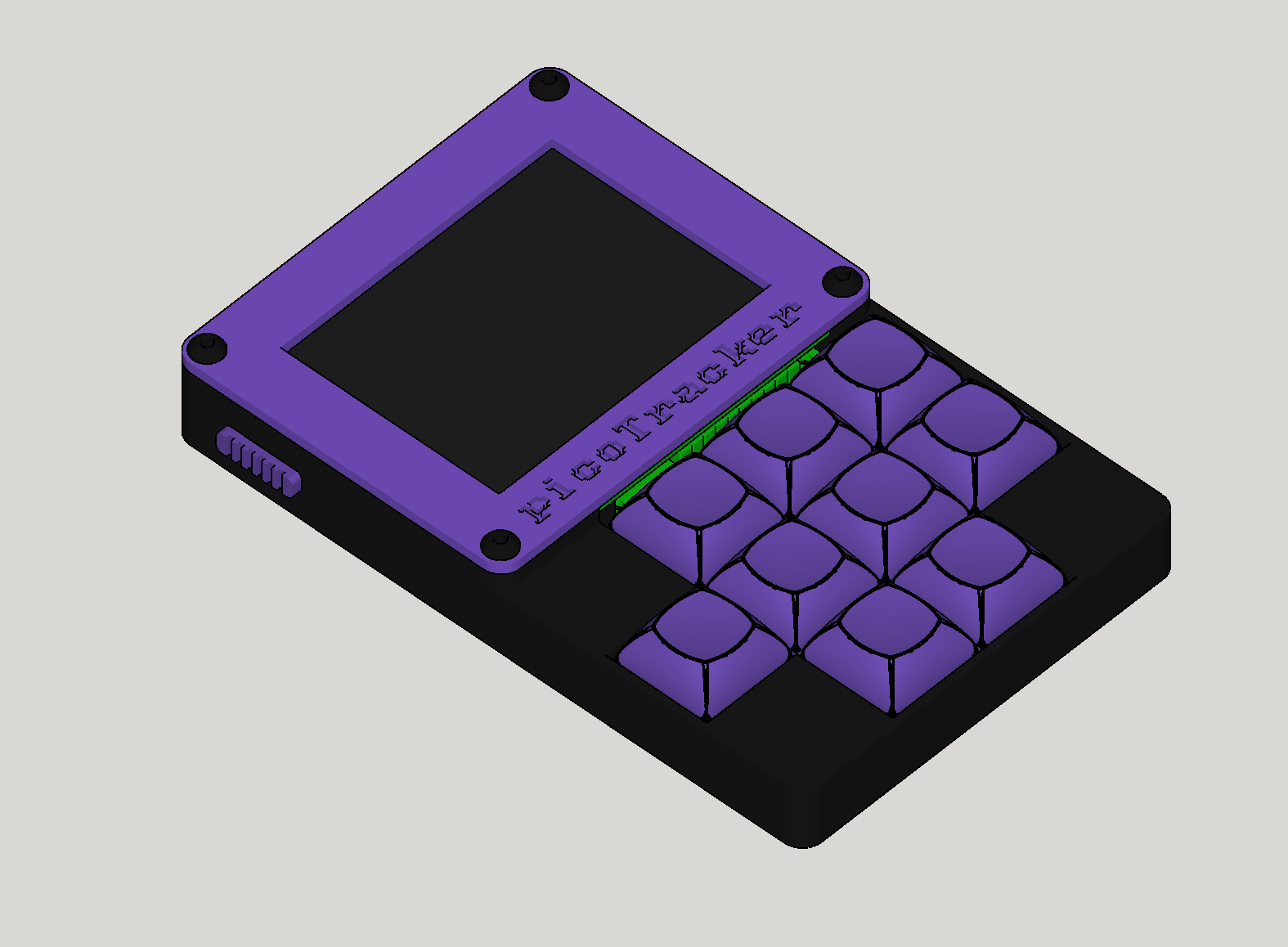
Final design
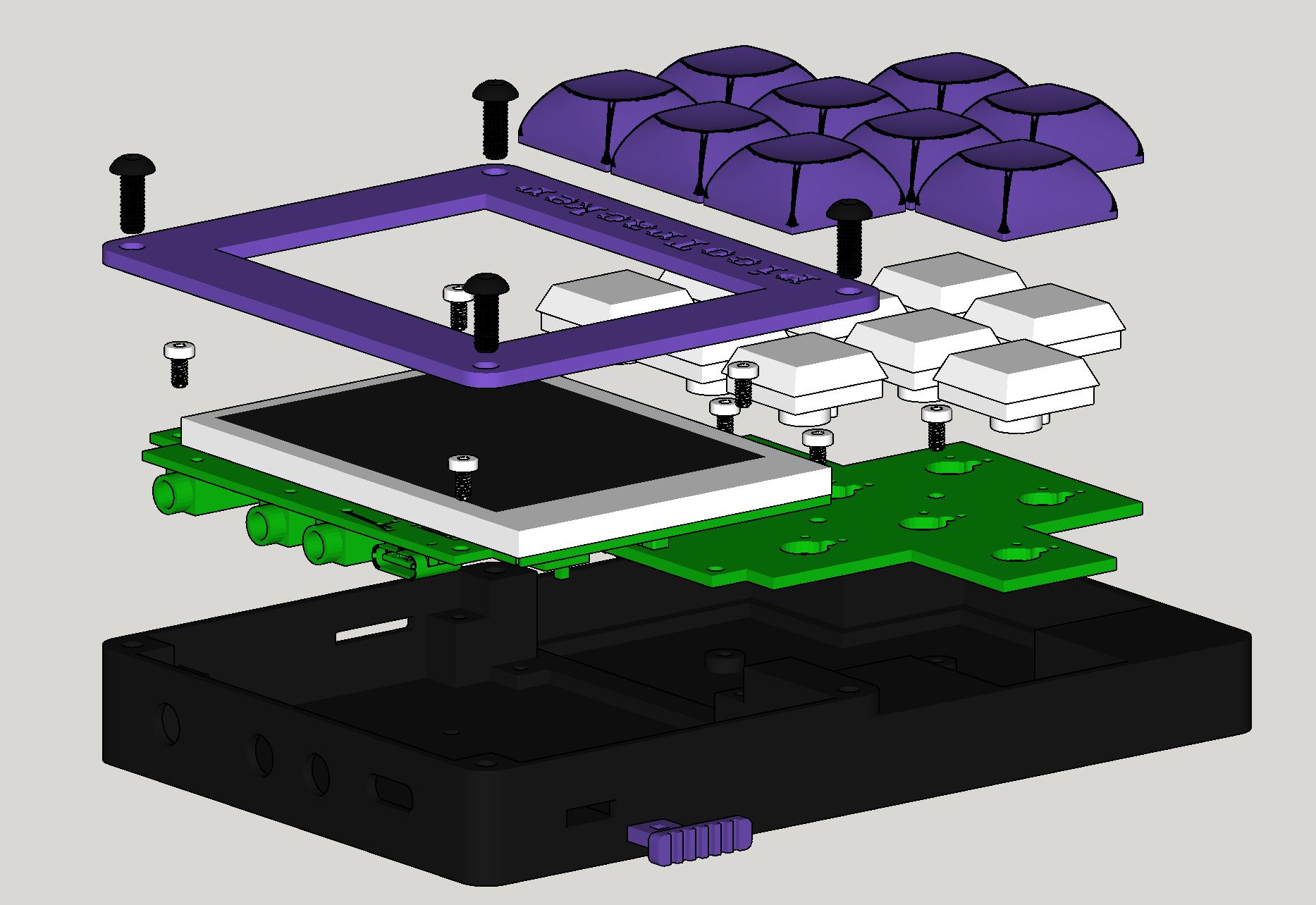
Exploded case
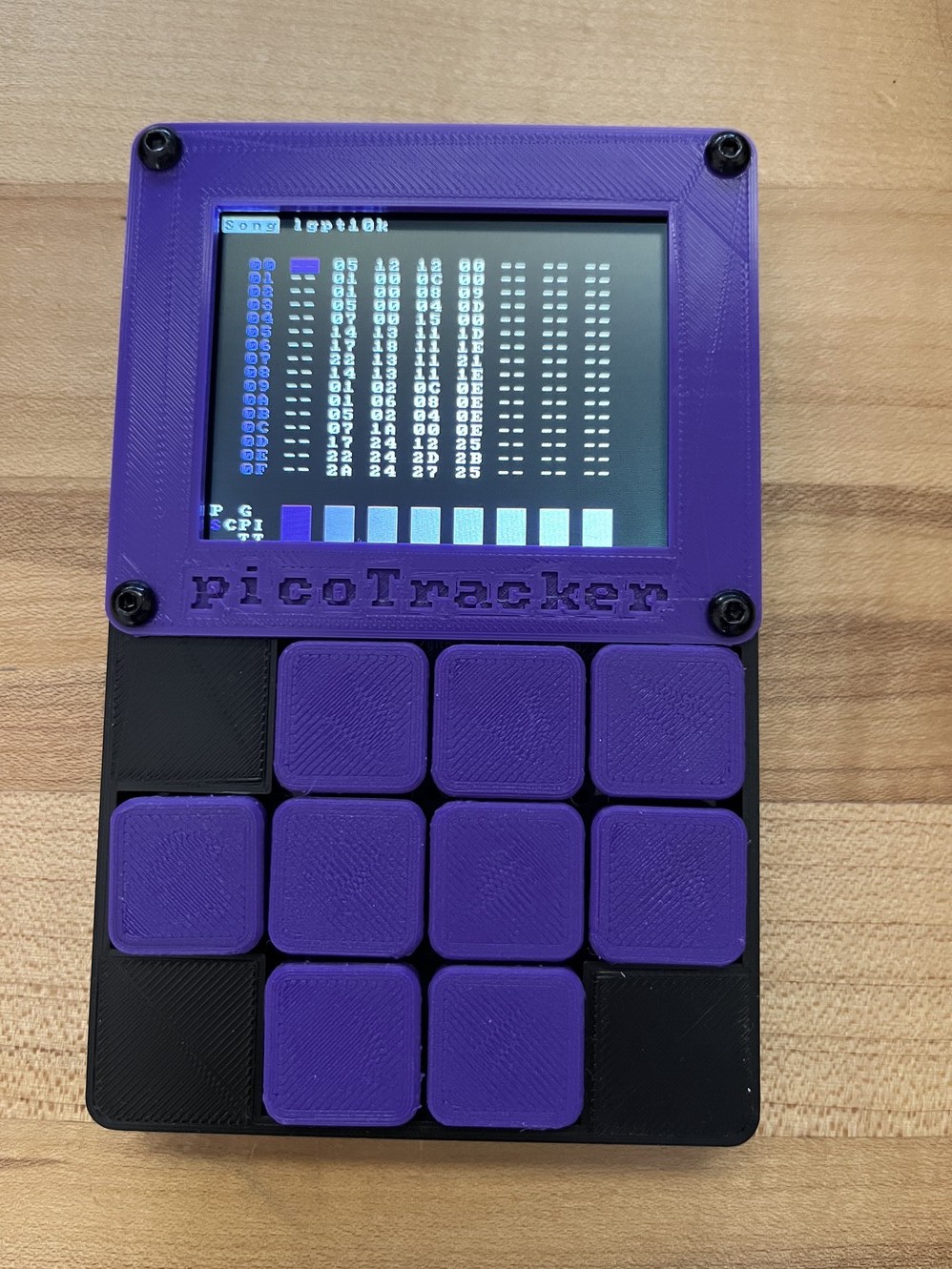
Original design with the 602535 battery and 3D printed keys
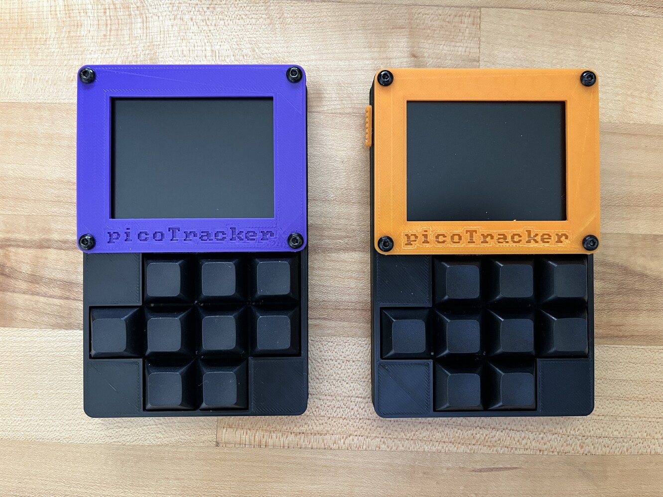
Playing with different colors, but the *official* color is purple. Given that the keycaps in the final design are not 3D printed it might be hard to match Bezel and keycaps colors. Black or some other unrelated color can be a good alternative
PCB
Layout was mostly decided according to the space available, on the top there is USB power (and potential future MIDI or whatever), MIDI In/Out and Headphone/Line out. On one side there is the SD card slot and on the other an on/off switch. At the bottom of the case there is a hole in order to reach the BOOTSEL switch, if needed. It’s built in two pieces, a very simple one for the switches and a second one with all the components. All components are on one side, and the other side is occupied by the display. Both boards are attached using standard 2.54 pitch male header pins. I tried to find some kind of connector better suited for this, for example something that is detachable, but couldn’t find anything very convenient. Cost of producing the PCB with assembly service came down to about 22 USD for 5 boards, including shipping.
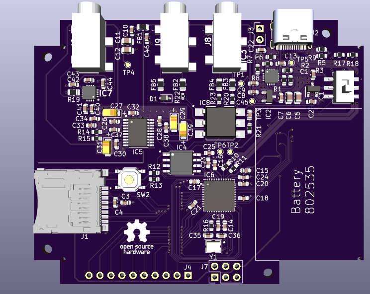
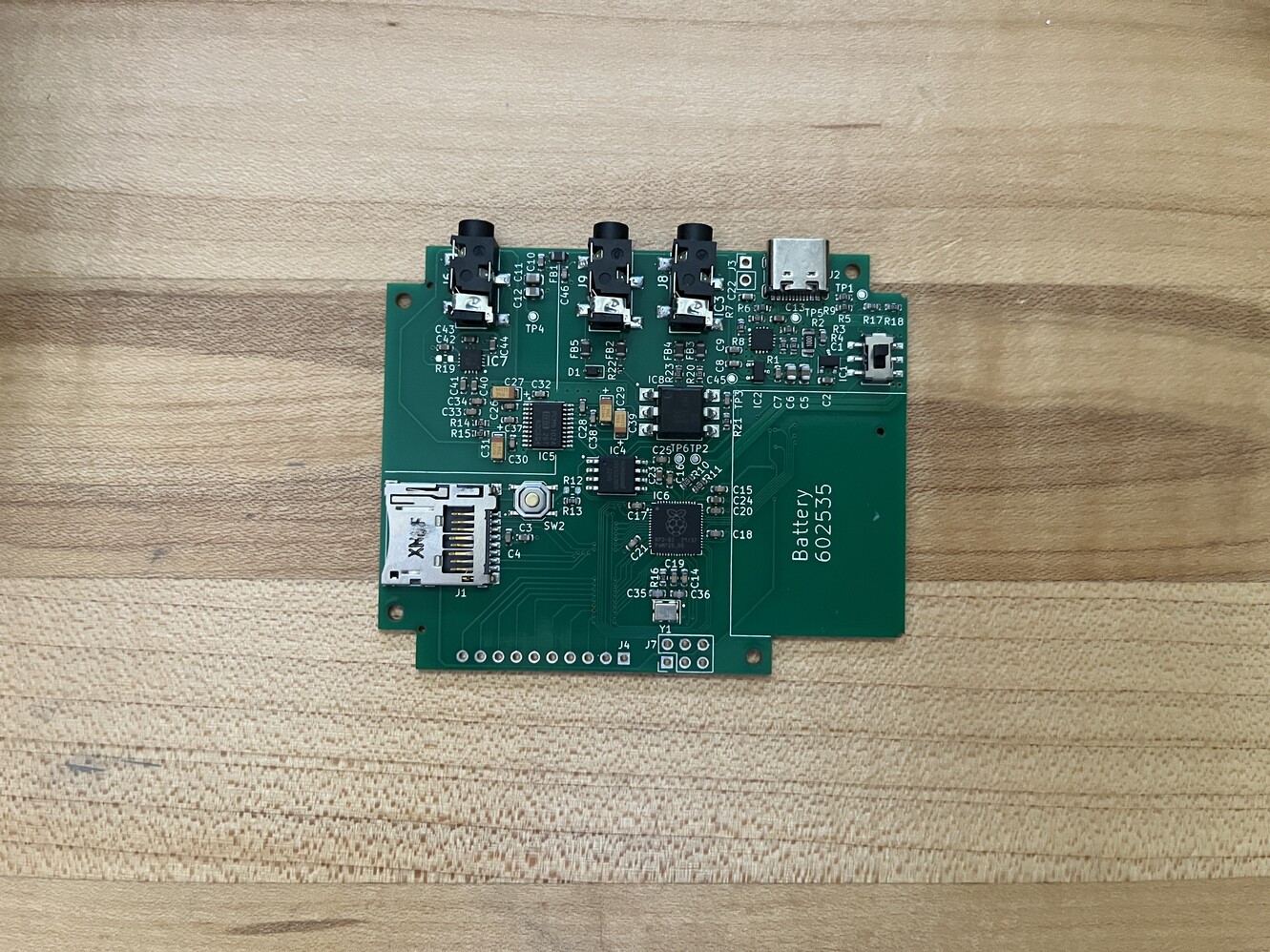
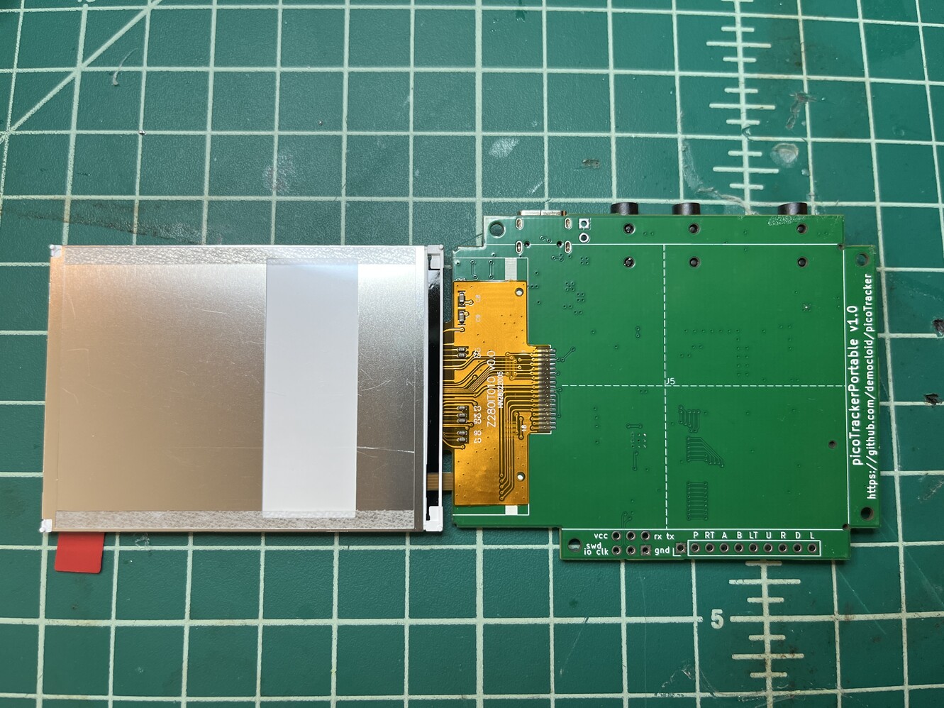
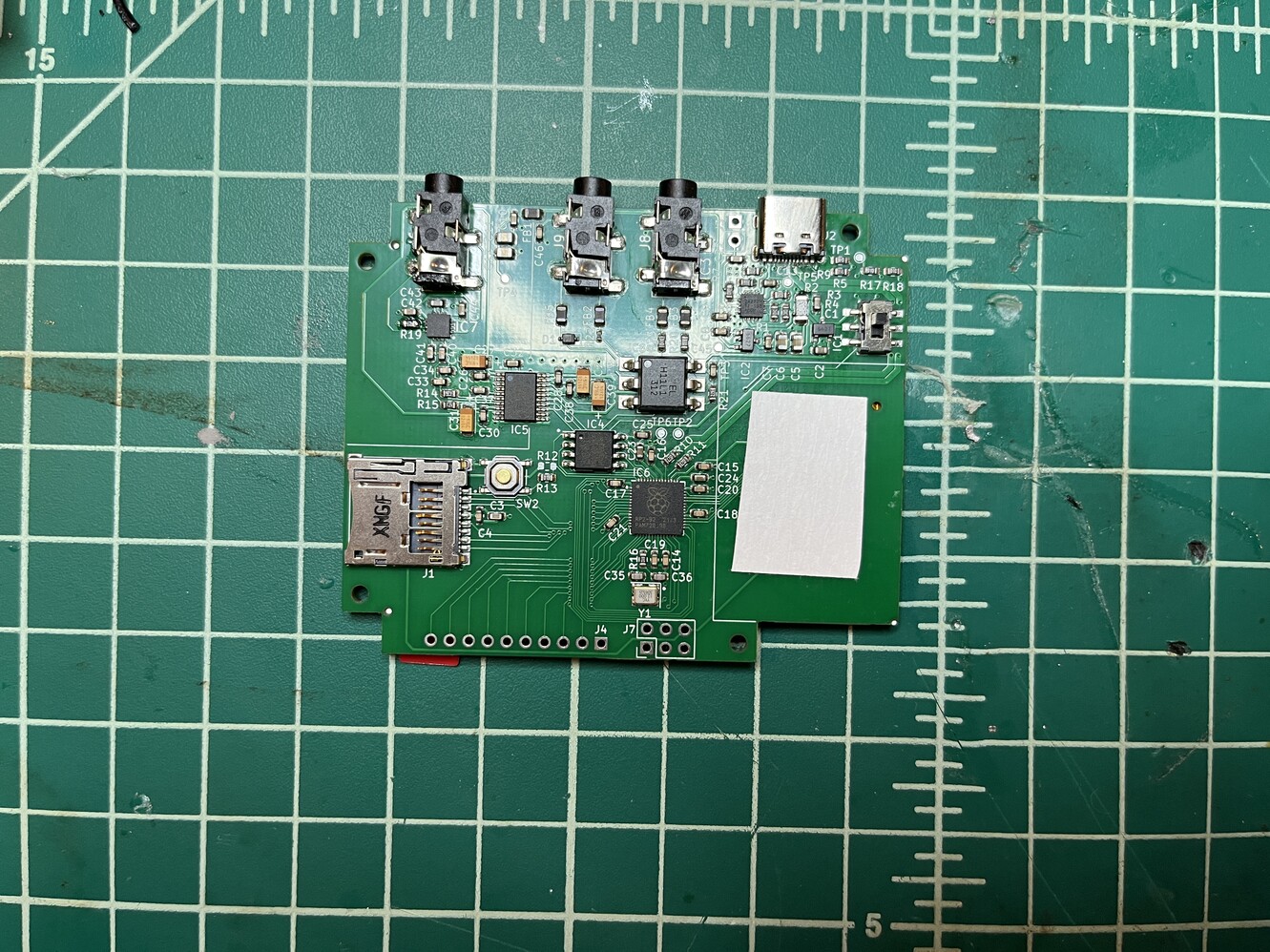
The back of the main board has all the components
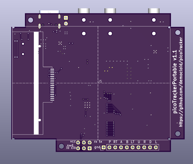
The top is where all the display goes, there's not much space for anything else
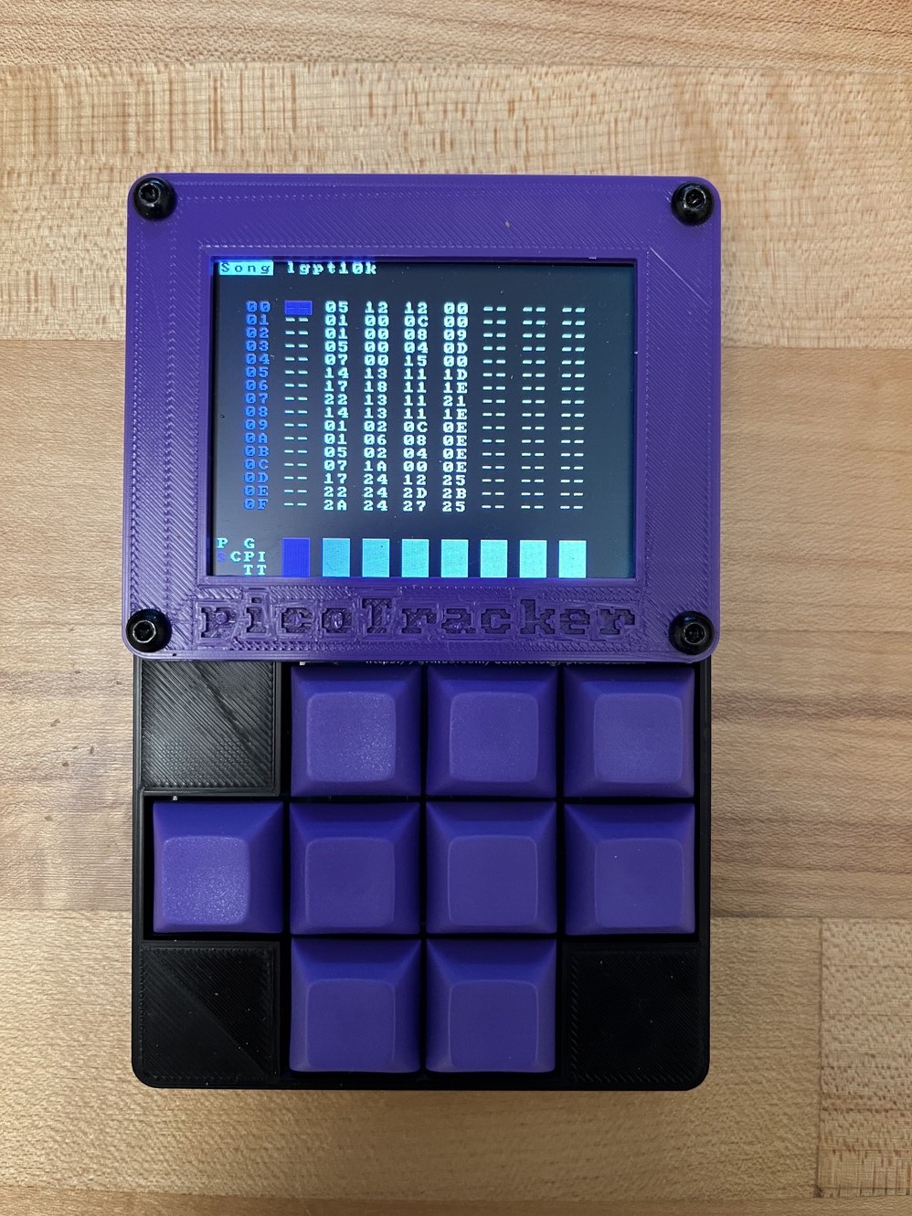
Final product
Assembly
Some pictures on how the final product is built and assembled into the case.
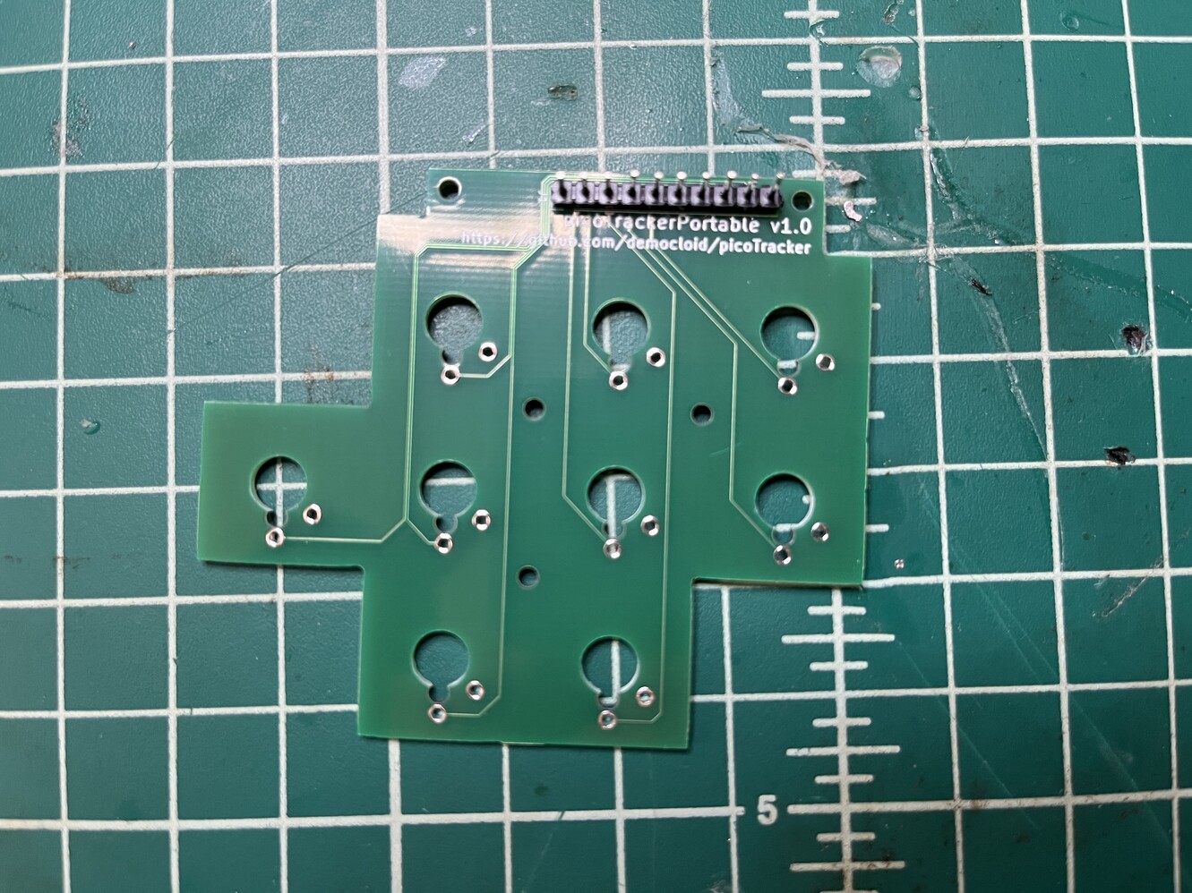
Attach standard male 2.54mm headers onto keypad PCB
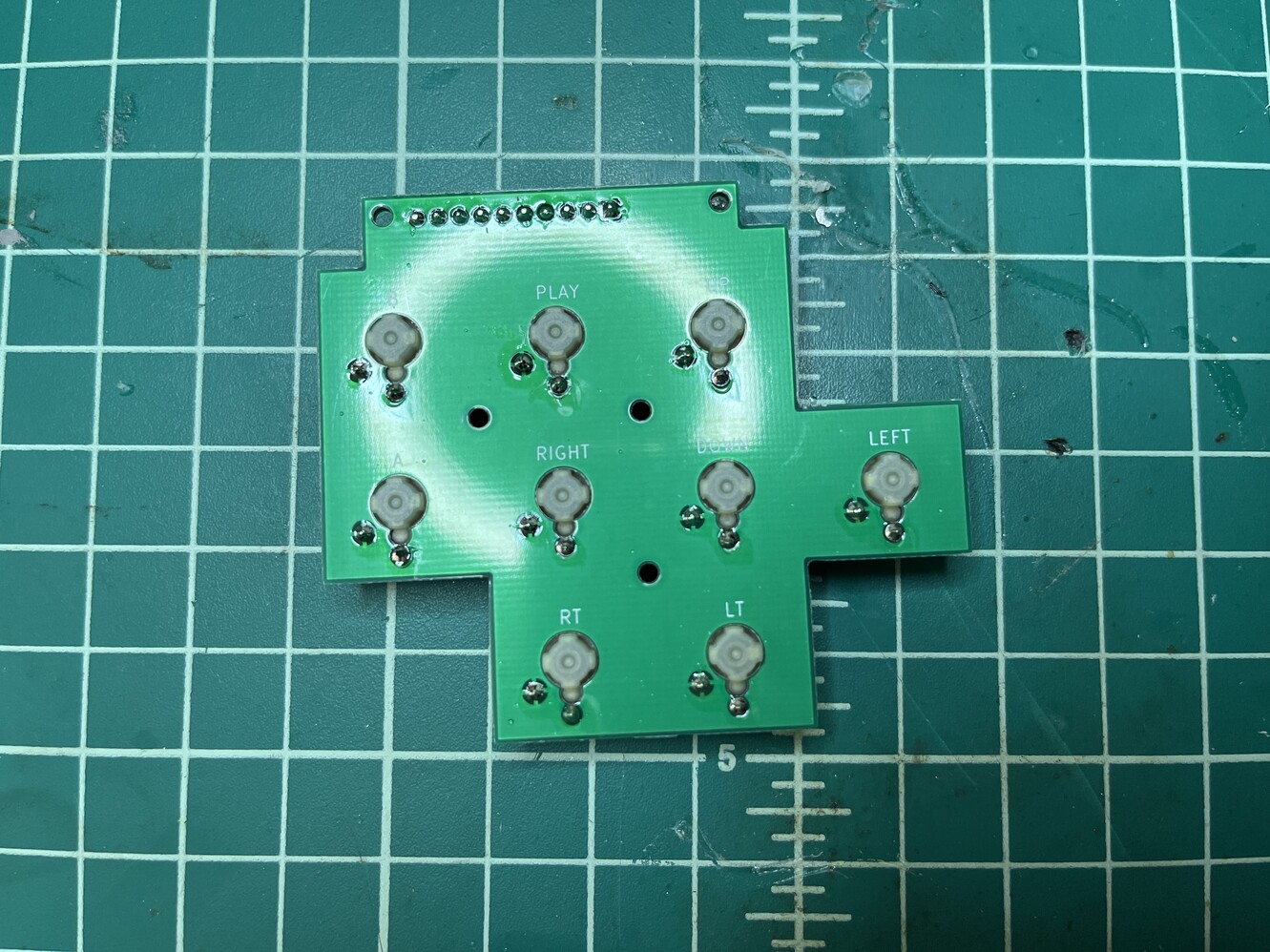
Solder the switches into it. Cherry low profile switches are used
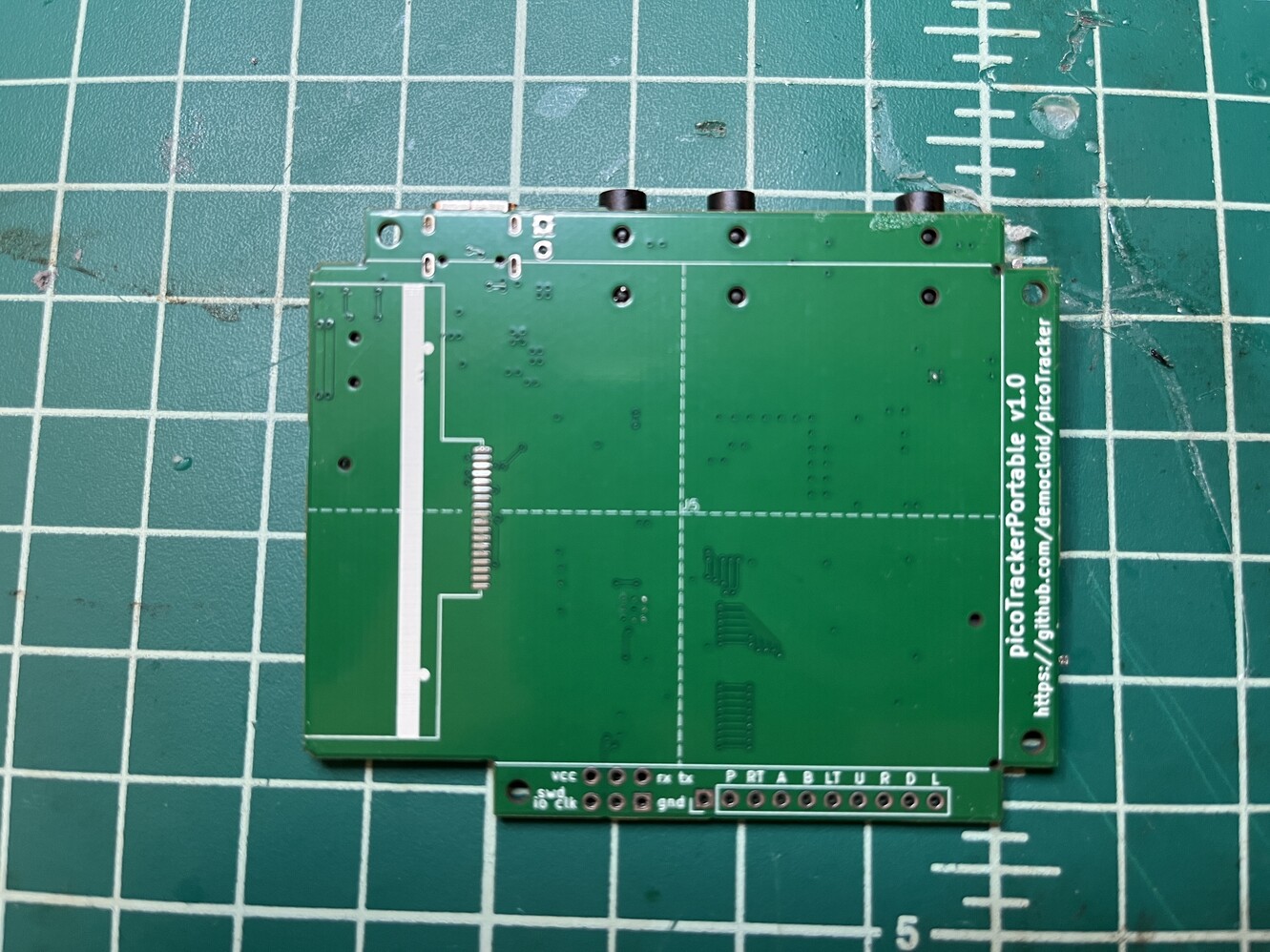
The back of the main PCB is dedicated to the display, the footprint shows how to align the flex cable for soldering and through holes align the display on final assembly
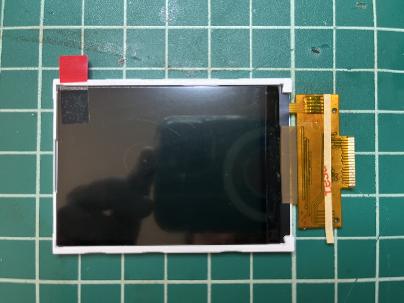
Display pre assembly
Adhesive cover is peeled off and flex cable aligned onto the PCB for soldering
On the other side of the PCB we need to attach the battery. Used double sided tape
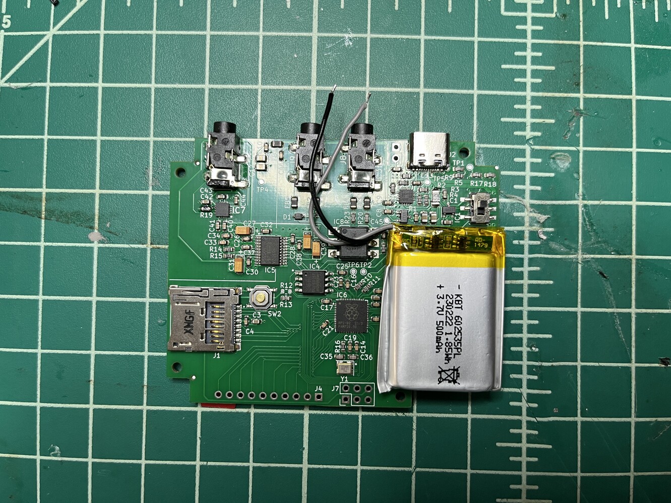
Battery in place
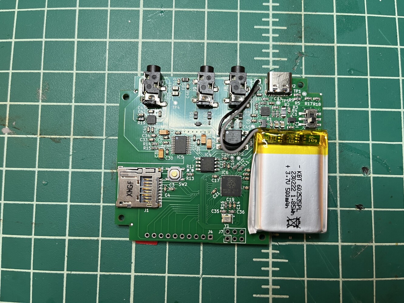
Cables soldered
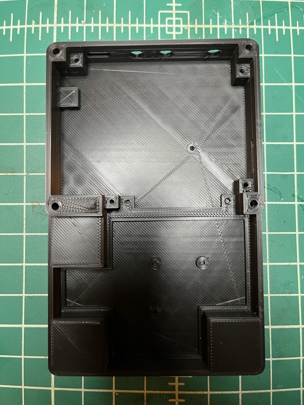
Ready to put the components in the case
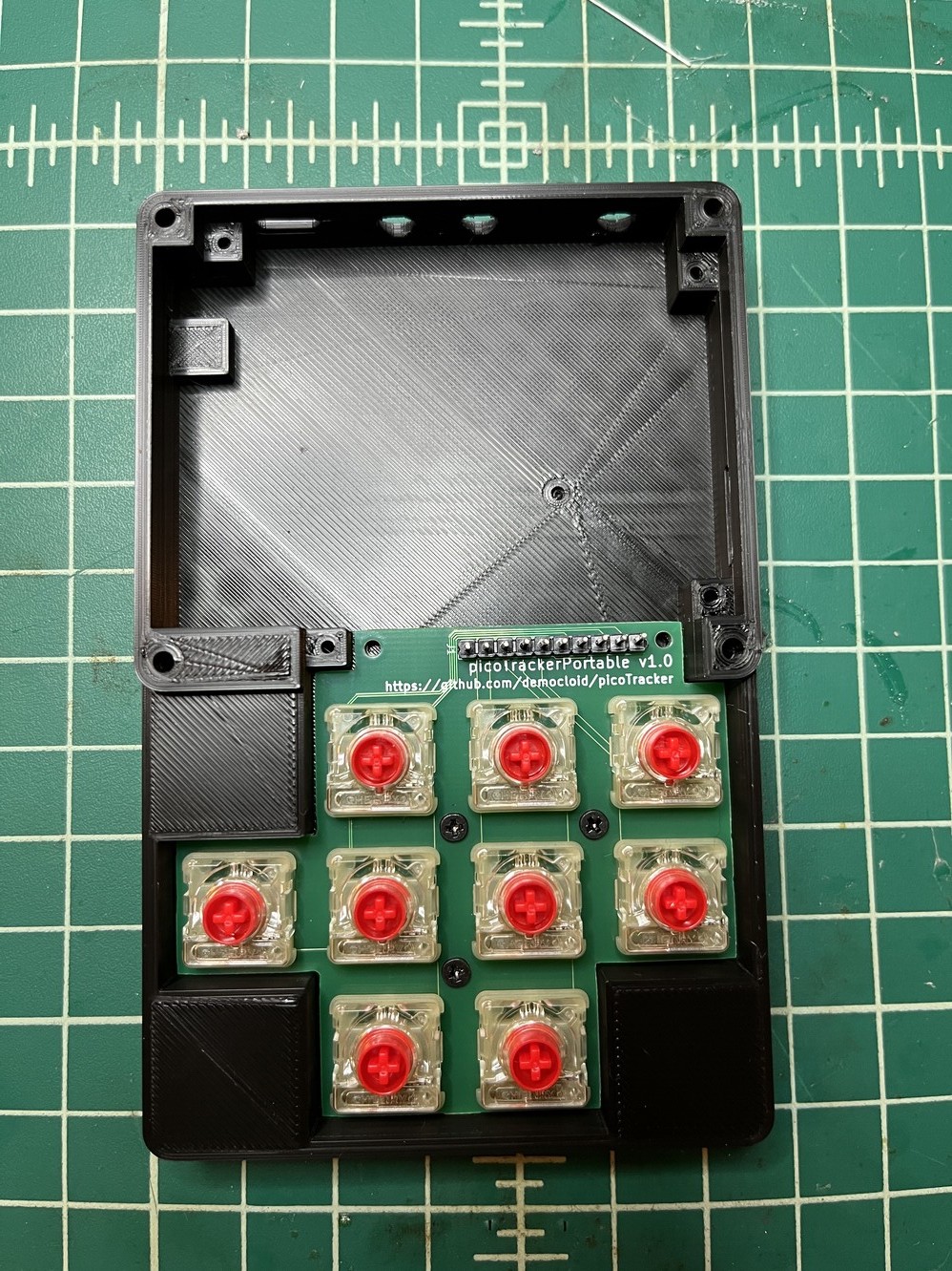
Keypad PCB goes first
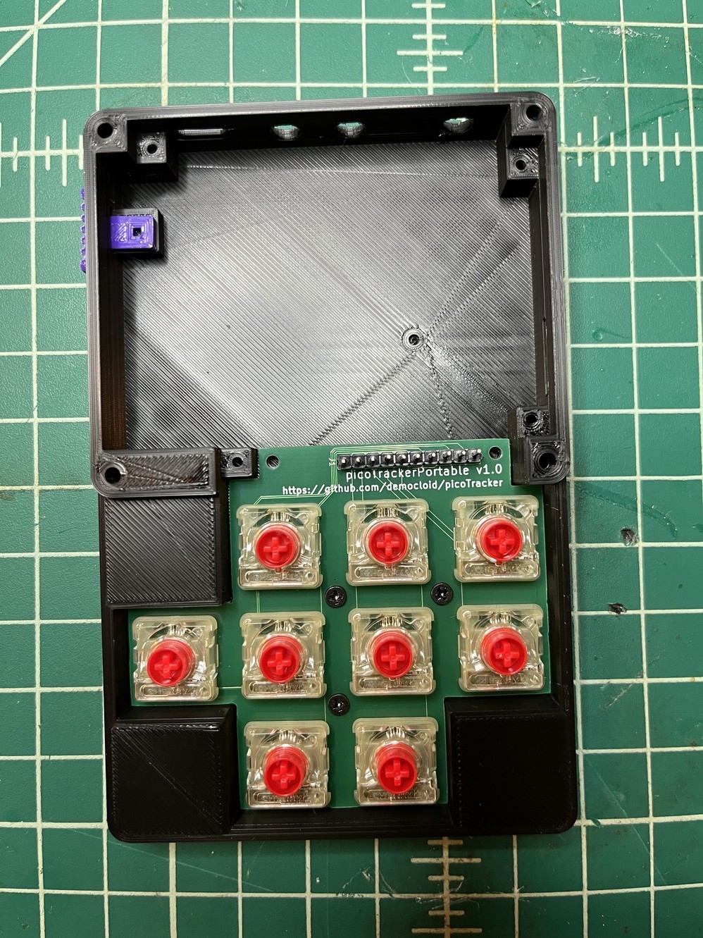
Before placing the main PCB, we need to put the power on switch in place
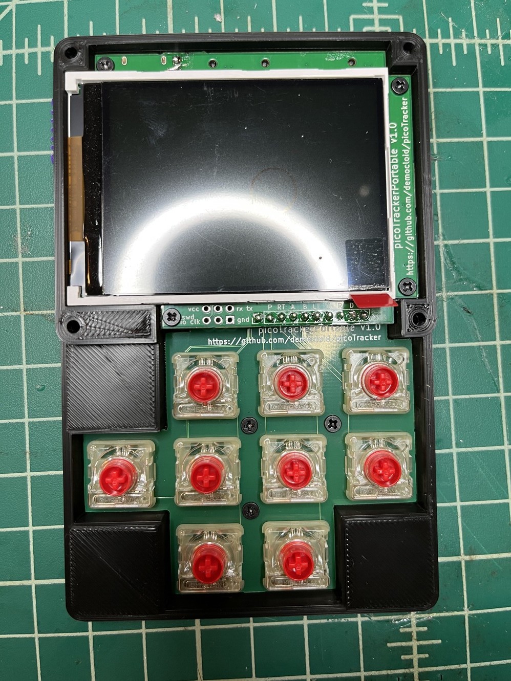
Place main PCB and solder headers in place. Done! The rest is cosmetic, install switches and screw in the bezel
Future: power optimization
When I was building picoTracker I never cared much about power consumption, since it wasn’t going to be a mobile platform. When I started to go in that direction I measured consumption and determined that it wasn’t too high, so it would be feasible to build this and have some decent battery life. Still, I may have done something wrong because it turns out that battery lasts less than I expected, still decent tho. There are a couple of things that could be done to improve this.
Hardware
- Improve power supply: right now it’s just simple LDO regulators, so it’s probably ~70% - 80% efficient, according to my calculations. Potentially worse.
- Brightness control of LCD: The backlight of the LCD is fixed to VCC. There are some pins left to be able to actually set brightness through PWM.
- Power down devices when not in use: DAC and headphone amp could be shut down when not playing, unsure if and how much this would save.
Software
- Reduce CPU frequency when not needed: picoTracker currently runs at 220.5MHz, which is needed to render all tracks. But this is only needed when playing sounds, when editing tracks and even playing single samples (i.e. when previewing samples) it could probably run 1/4 or 1/8 frequency without affecting the workflow much. Tested this briefly and it saves quite a bit of power.